Frame structure for vehicle

a frame structure and vehicle technology, applied in the direction of roofs, vehicle arrangements, transportation and packaging, etc., can solve the problems of lateral buckling under a generally constant crushing reaction (force), the strength/rigidity of the floor member tends not to meet the impact deformation requirements, and the transfer of lateral buckling toward the section b owing to the formation of an abrupt change in lateral rigidity

Inactive Publication Date: 2001-10-18
NISSAN MOTOR CO LTD
View PDF0 Cites 15 Cited by
  • Summary
  • Abstract
  • Description
  • Claims
  • Application Information

AI Technical Summary

Problems solved by technology

As a result, the strength / rigidity of the floor member tends not to satisfy impact deformation requirements.
This causes the rigidity of the part C.sub.1 to be smaller than that of the part C.sub.2, which results in part C.sub.1 laterally buckling under a generally constant crushing reaction (force).
As a result, the transfer of lateral buckling toward the section B owing to the formation of abrupt change in lateral rigidity is restricted.
Therefore, when the part C.sub.2 stably buckles with a substantially constant crushing reactive force to weaken the impact force, the part C.sub.1 is successively subjected to a stable buckling deformation with a substantially constant crushing reactive force without an accompanying rise in reactive force, and thus weakens the impact force.

Method used


Image

  • Frame structure for vehicle
  • Frame structure for vehicle
  • Frame structure for vehicle

Examples


second embodiment

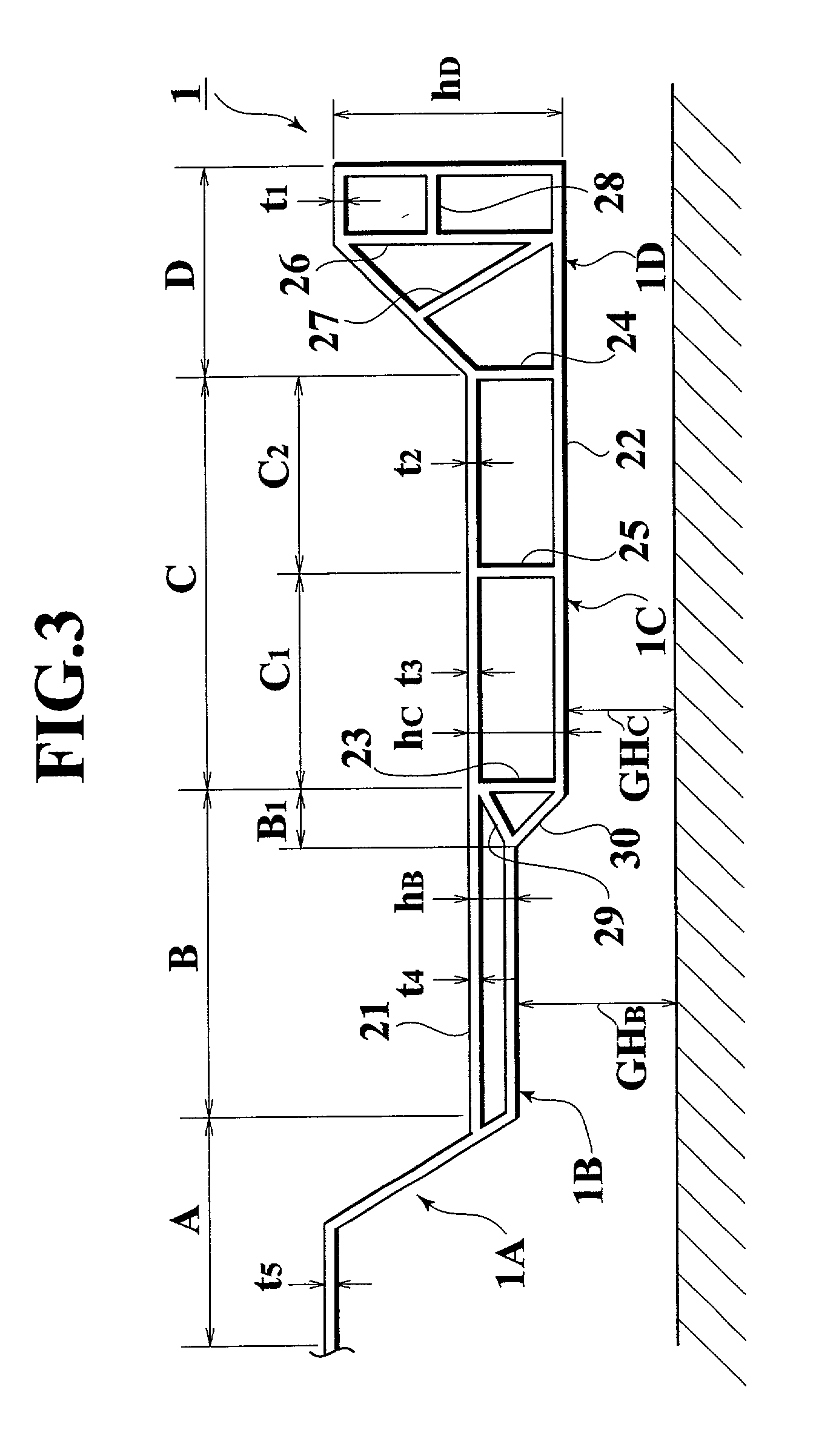
[0066] FIG. 11 shows the present invention. In this embodiment, the tunnel section 1A is also formed of a single wall, while the remaining parts 1B, 1C, 1D are respectively formed to have closed cross-sections composed of the upper and lower walls 21, 22, the partition ribs 23, 24, 25 and the reinforcement ribs 26 to 30. Further, the closed cross-sectional heights of sections B, C, D, are also such that h.sub.D>h.sub.C>h.sub.B.

[0067] In the above-mentioned basic structure, the physical characteristics of sections A to D of the second embodiment are quite similar to the first embodiment. However, in section C, the wall thickness t.sub.6 of the upper wall 21 in the section C is greater than the wall thickness t.sub.7 of the lower wall 22 in the same section due to the requirements of floor rigidity against the seat loads (t.sub.6

[0068] In the case of different wall thicknesses t of the inner and outer walls 21, 22 in section C, it is necessary that the inner and outer walls ...

third and fourth embodiments

[0070] FIGS. 12 and 13 show modifications of the high-strength part B.sub.1 while FIG. 14 shows the deformation produced by a side impact.

[0071] In FIG. 12, section B is formed so that the wall thickness t.sub.4A, t.sub.9A of the high-strength part B.sub.1 are larger than the wall thickness t.sub.4, t.sub.9 of the other parts except for the high strength part B.sub.1. Also in FIG. 13, section B is formed so that the wall thickness t.sub.4A, t.sub.9A, t.sub.9B of the high-strength part B.sub.1 is greater than the wall thickness t.sub.4, t.sub.9 of the other part which the exception of the high strength part B.sub.1. However, the average lateral rigidity of the section B including the high-strength part B.sub.1 is substantially similar to or less than that of the section C. As shown in FIG. 14, when the vehicle is subjected to side impact, the deformation is abruptly decreased upon reaching the outboard edge of the high-strength part / section B.sub.1.

[0072] As mentioned above, the floo...


PUM


Abstract

A frame structure capable of increasing collision energy absorption includes a floor member. The floor member has extruded side sill members which are adapted to undergo lateral buckling response to side collisions while resisting axial or longitudinal deformation due to end-on collisions. Extruded impact dispersing deformable sections with a smaller rigidity than the associated side sills are provided on the inboard sides of the sills and arranged to smooth buckling and disperse collision energy. At least one extruded, flat, passenger occupancy floor section, which is located inboard of the impact dispersing deformable sections, is provided to prevent buckling deformation and assure cabin space.

Description

[0001] 1. Field of the Invention[0002] The present invention generally relates to a frame structure for a vehicle and, more particularly, to a frame or chassis arrangement having a floor structure formed from a corrosion resistant, lightweight extrudable material.[0003] 2. Description of the Related Art[0004] Japanese Unexamined Patent Publication (kokai) No. 11-272994 discloses an automotive frame structure wherein a floor member is extruded from a lightweight metallic material, such as an aluminum alloy, so as to have an elongated closed hollow cross-sections extending in the fore-and-aft (longitudinal) direction of the vehicle body. In this conventional frame structure, however, the extruded floor member has a constant closed cross-sectional height and a constant wall thickness. As a result, the strength / rigidity of the floor member tends not to satisfy impact deformation requirements.[0005] It is an object of the present invention to provide a frame / chassis structure for a vehic...

Claims


Application Information

Patent Timeline
Patent Type & Authority Applications(United States)
IPC IPC(8): B62D21/15B62D25/20B62D29/00
CPCB62D21/15B62D21/157B62D25/025B62D25/20B62D25/2036B62D29/008
Inventor MIYASAKA, HIROYUKI
Owner NISSAN MOTOR CO LTD
Why Eureka
Try Eureka