
Device for holding cams during their binding on a tube by expansion of the tube

a technology of expansion tube and camshaft, which is applied in the direction of mechanical equipment, manufacturing tools, metal-working machine components, etc., can solve the problems of cam cracking, cam manufacturing precision being insufficient, and cams are less resistant to sintered cams than cams

Inactive Publication Date: 2001-10-04
PMG INDIANA CORP +1
View PDF0 Cites 10 Cited by
  • Summary
  • Abstract
  • Description
  • Claims
  • Application Information

AI Technical Summary

Benefits of technology

[0013] An object of the present invention is to provide a device for holding the cams during their binding on a tube, which enables obtaining a camshaft that requires no rectification.
[0015] According to an embodiment of the present invention, the device includes means for preventing a play from appearing between the two blocks associated with a cam during the tube expansion.

Problems solved by technology

The cam manufacturing precision being insufficient, it is necessary to rectify the cams after their binding on the tube, to restore the required dimensions.
Indeed, sintered cams are less resistant than cams obtained by other methods and risk cracking during the binding if they are not held along their entire circumference.
Despite these precautions, some cams still appear to have a bad angular position and must be rectified.

Method used


Image

  • Device for holding cams during their binding on a tube by expansion of the tube
  • Device for holding cams during their binding on a tube by expansion of the tube

Examples


Embodiment Construction

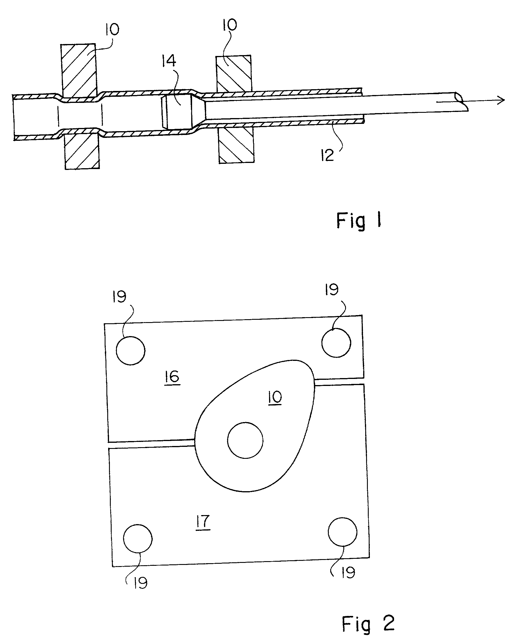
[0022] The present invention is based on an analysis of the phenomena occurring during the binding when using a cam holding device of the type in FIG. 2.

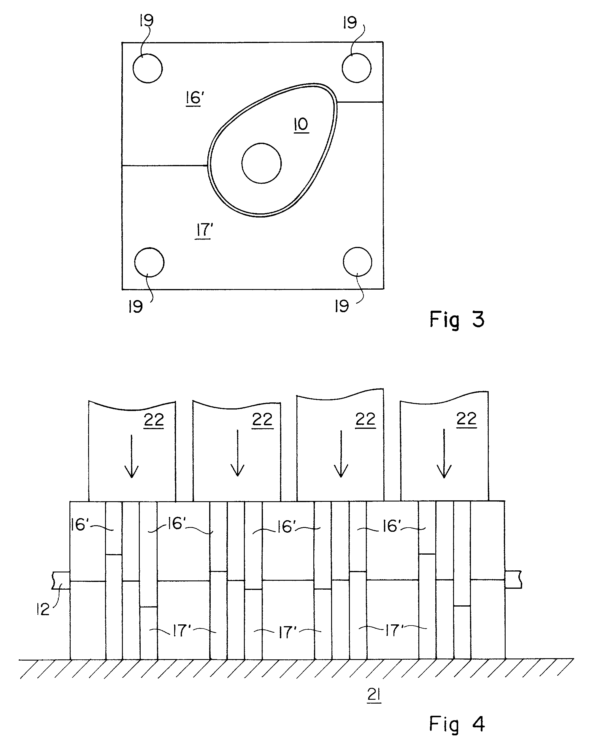
[0023] When several juxtaposed blocks of the type in FIG. 2 are used to hold several cams along a tube, the cams having the smallest dimensions in the admitted tolerance range appear to be arranged with a play between their blocks. Indeed, when the two half-cases formed by the juxtaposition of the blocks bear against each other, only two cams are held with no play between their two blocks. However, the other cams, held with a play, do not crack. This shows that a certain peripheral play can be left between the cam and the two blocks without risking breakage during the binding.

[0024] The present invention provides suppressing the play at the level of the parting line and holding all cams with a peripheral play. Conversely to what could be expected, the accuracy of the angular positioning is thus improved.

[0025] FIG. 3 shows an exampl...


PUM


Abstract

A device for holding sintered cams during their binding on a tube by expansion of the tube, including, for each cam, two blocks intended for enclosing the cam in housings complementary to the cam contour. The dimensions of the housings are chosen so that the play between the housings and the largest cam within a predetermined tolerance range is as close to zero as possible by excess, the two blocks being provided to bear against each other whatever the dimensions of the cam within the tolerance range.

Description

BACKGROUND OF THE INVENTION[0001] 1. Field of the Invention[0002] The present invention relates to the forming of a camshaft by binding the cams on a tube by expanding the tube. It more specifically relates to a device for holding the cams during the binding.[0003] 2. Discussion of the Related Art[0004] FIG. 1 schematically illustrates cam being secured on a tube such as described, for example, in U.S. Pat. No. 4,597,365. Several cam 10 are arranged around a tube 12 that initially engages with a slight play in bores of cam 10. Cams 10 are held at desired axial and angular positions by a holding device not shown in FIG. 1.[0005] A tube expander 14 is engaged in tube 12, and its diameter is such that the external diameter of tube 12 is enlarged to become slightly greater than the internal diameter of cams 10. This results, as shown in the left-hand portion of FIG. 1, in a permanent deformation of the tube and a binding thereof in the bores of cams 10.[0006] In the above-mentioned US p...

Claims


Application Information

Patent Timeline
IPC IPC(8): B21D53/84
CPCB21D53/845Y10T29/53996Y10T29/49293Y10T29/53961Y10T29/4994
Inventor GUEYDAN, HENRI
Owner PMG INDIANA CORP
Learn More