
Process and flotation device for the removal of intereering materials from an aqueous fiber pulp suspension

a technology of interfering materials and flotation devices, which is applied in the direction of flotation, solid separation, wet end machines, etc., can solve the problems of difficult separation of suspensions, bubbles only having to travel a very short distance, and weakening effects

Inactive Publication Date: 2001-08-02
VOITH PATENT GMBH
View PDF0 Cites 7 Cited by
  • Summary
  • Abstract
  • Description
  • Claims
  • Application Information

AI Technical Summary

Benefits of technology

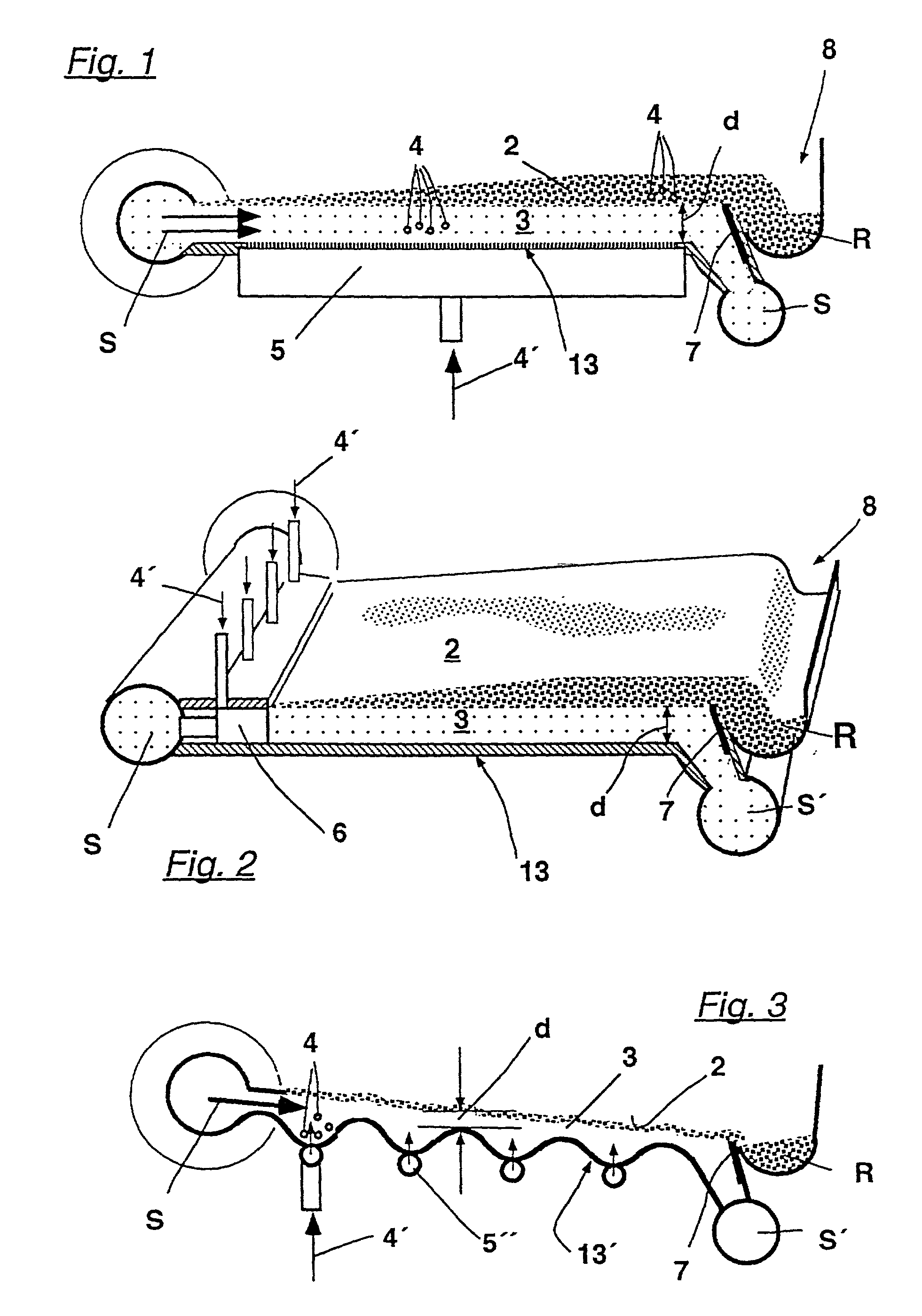
[0008] By the present invention, the difficulties, caused by the high viscosity of the suspension, can be overcome. The gas bubbles, loaded with interfering materials, have an increased resistance while reaching from the suspension into the flotation foam by following their tendency to rise. However, because of the fact that the flotation process is executed with a relatively thin flotation layer, the gas bubbles only have to travel a very short distance. In embodiments of the process in accordance with the invention, the gas bubbles' tendency to rise can be enhanced by applying a gravity field which is greater than earth's gravity. Another possibility makes provisions to accelerate the rise of the gas bubbles with the aid of impulses or vibrations.
[0018] A further feature is to create a micro-turbulence in the suspension prior to the initial processing and to accelerate the suspension to at least twice the average flow velocity during the entry into the flotation layer.

Problems solved by technology

However, the effect weakens when the amount of fibers in the suspension is relatively high, for example 2 %, instead of the conventional amount of around or below 1 %.
In such cases problems often occur since the resistance for the gas bubbles is already high with a higher fiber content, thereby making it difficult to separate the suspension.
However, because of the fact that the flotation process is executed with a relatively thin flotation layer, the gas bubbles only have to travel a very short distance.

Method used


Image

  • Process and flotation device for the removal of intereering materials from an aqueous fiber pulp suspension
  • Process and flotation device for the removal of intereering materials from an aqueous fiber pulp suspension
  • Process and flotation device for the removal of intereering materials from an aqueous fiber pulp suspension

Examples


Embodiment Construction

.

[0038] The particulars shown here are by way of example and for purposes of illustrative discussion of the embodiments of the present invention only and are presented in the cause of providing what is believed to be the most useful and readily understood description of the principles and conceptual aspects of the present invention in more detail than is necessary for the fundamental understanding of the present invention, the description taken with the drawings making apparent to those skilled in the art how the several forms of the present invention may be embodied in practice.

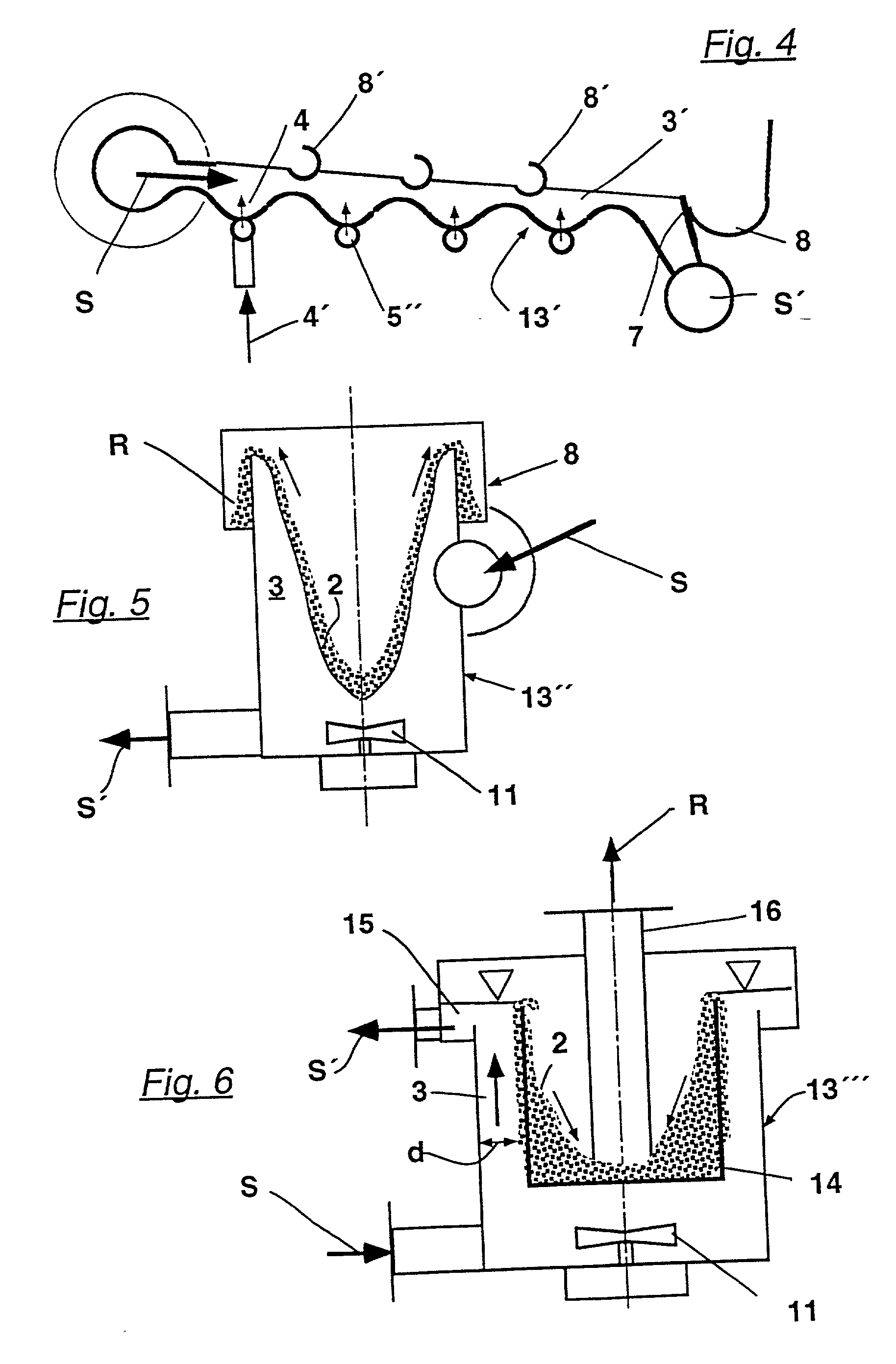
[0039] The basic steps of the embodiment of the process in accordance with the invention are shown in FIG. 1. The fibrous pulp suspension S is fed into a flotation device. A flotation layer 3 with a thickness d of no more than 100 mm is created in a flotation vessel 13. This thickness is specified by a dividing or separating element 7, which is here provided as a height-adjustable foam weir over which the fl...


PUM

PropertyMeasurementUnit
Lengthaaaaaaaaaa
Lengthaaaaaaaaaa
Lengthaaaaaaaaaa

Abstract

The process is designed for the flotation of interfering materials from an aqueous fibrous pulp suspension and is in particular used in the processing of printed or used paper that is otherwise contaminated. The separation of gas bubbles of the suspension occurs in a flotation layer that has a maximum thickness of approximately 100 mm. The process also achieves good flotation results in fibrous pulp suspensions that have a fiber pulp content significantly larger than 1 % by weight, for example around 2% by weight. A flotation apparatus is provided for performing the flotation process. The apparatus includes a flotation vessel, an inlet, an outlet, and a skimmer device.

Description

[0001] The present application is a continuation of U.S. patent application Ser. No. 08 / 115,672 filed Jul. 15, 1998, which claims the priority under 35 U.S.C. 119 of German Patent Application No. 197 30 464.8, filed on Jul. 16, 1997, the disclosures of which are expressly incorporated by reference herein in their entireties.[0002] 1. Field of the Invention[0003] The invention relates to a process and apparatus for the removal of interfering materials from an aqueous fiber pulp suspension.[0004] 2. Discussion of Background Information[0005] Processes of the aforementioned type are used in order to remove at least a portion of the interfering pulp particles suspended in a fibrous pulp suspension containing fiber pulp. It is common knowledge that a foam or floating slurry, containing the material to be removed, is created in a flotation process. A typical case of application of such a process is the processing of aqueous fibrous pulp suspensions that are produced from printed used pape...

Claims


Application Information

Patent Timeline
IPC IPC(8): B03D1/02B03D1/14B03D1/24D21B1/32D21F1/70
CPCB03D1/02B03D1/1418B03D1/1425B03D1/1462B03D1/24D21B1/327D21F1/70B03D1/1493B03D1/16Y02W30/64
Inventor BRITZ, HERBERTGOMMEL, AXELHOLIK, HERBERTKEMPER, MARTINKRIEBEL, ALMUTMANNES, WOLFGANGREINHOLDT, BORISSTEINBILD, KLAUS
Owner VOITH PATENT GMBH
Learn More