Laminated hook fastener
- Summary
- Abstract
- Description
- Claims
- Application Information
AI Technical Summary
Benefits of technology
Problems solved by technology
Method used
Image

Examples
example ii
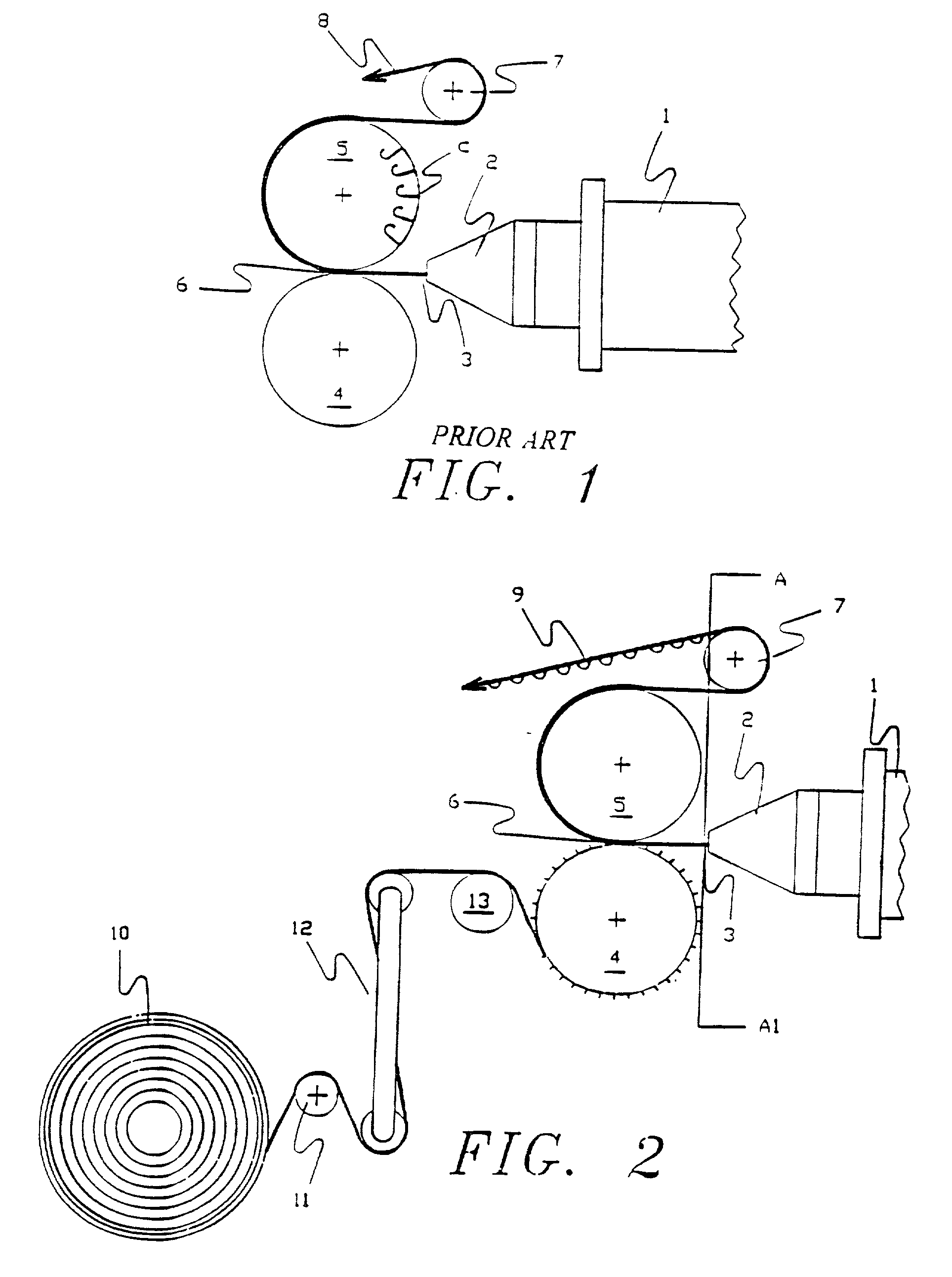
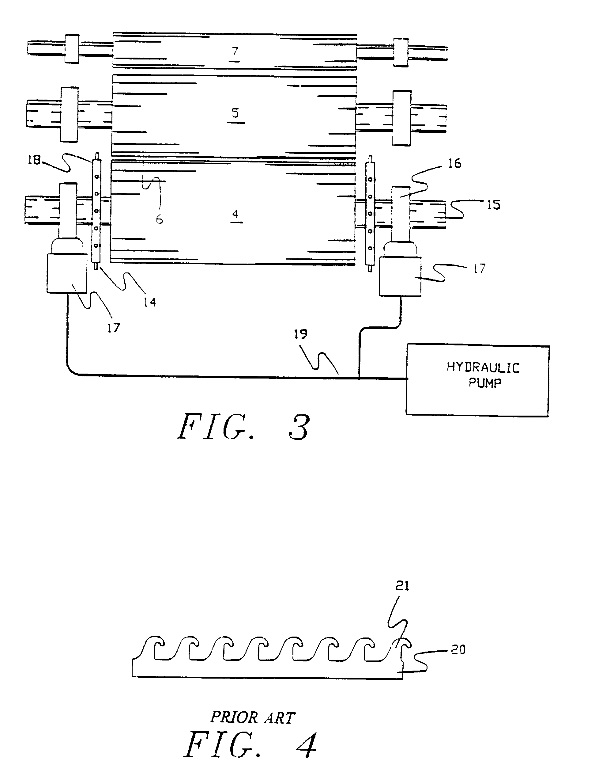
29. The apparatus described in U.S. Pat. No. 4,773,310 was set up to produce a plastic hook product designated as hook type CEM-15 by the Velcro Group Corporation, using a co-polyester resin sold by the DuPont Company, a Hytrel.sup.R 8238 with 10% of a master batch fire retardant added to provide fire resistance to the final product. The melt temperature of the polymer, at the end of the extruder, was 475.degree. F. and the die temperature was 476.degree. F. The line speed was 30 feet per minute. A roll of spunbonded nonwoven fabric, sold as Remay.sup.R 2016, weighing 1.35 ounces per square yard with a thickness of 0.009 inches was slit to 10 inches width and introduced into the nip formed by the bottom and forming rolls of the device as described in Example I. The bottom roll temperature was 50.degree. F., the forming roll temperature was 50.degree. F. and the top roll temperature was 90.degree. F. A tension of 100 pounds was exerted against the spun bonded fabric in order to preve...
example iii
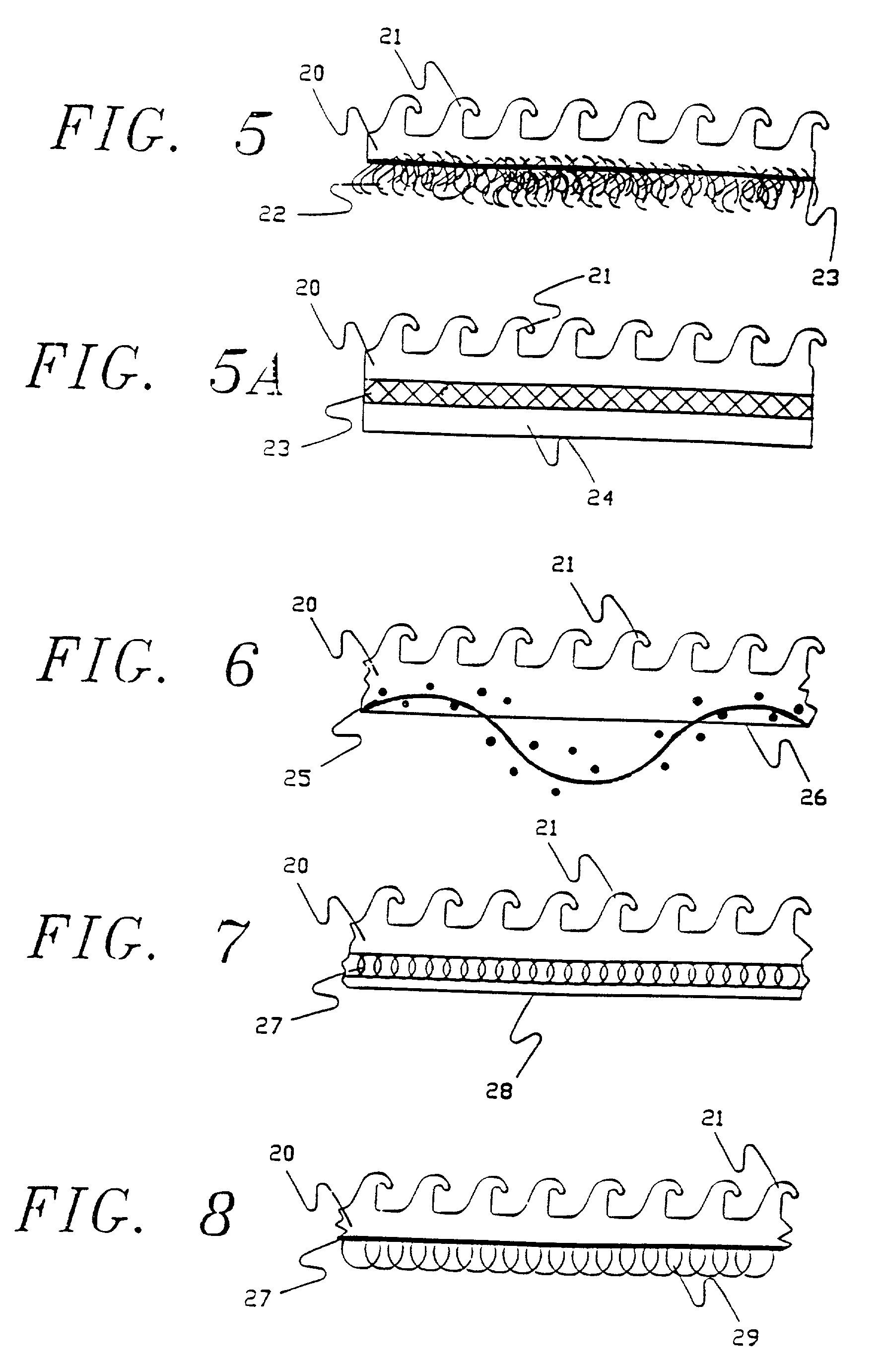
31. Exactly the same configuration as used in Example II was utilized but the spunbonded nonwoven used was a lighter weight version of Remay, designated as Remay.sup.R style 2006, weighing 0.6 ounces per square yard with a thickness of 0.006 inches. In order to eliminate wrinkles and folds from the web, tension was reduced to 25 pounds and the same overfeed was used on the bottom roller. The product formed by this combination was similar to that of Example II but the mingling of the polymer into the interstices of the nonwoven was greater than in that example, but it was still possible to raise fibers from the surface by vigorous rubbing, and there were many fibers on the surface of the plastic projecting as a very fine fuzz above the surface.
example iv
32. Exactly the same configuration as used in Examples II and III were utilized but the spunbonded nonwoven used was even lighter then in the previous examples. The version of Remay in this example was designated as Remay.sup.R style 2250, weighing 0.5 ounces per square yard with a thickness of 0.004 inches. In order to eliminate wrinkles and folds from the web, tension was reduced to 20 pounds and the overfeed was increased to 9% on the bottom roller. The product formed by this combination was similar to those of Examples II and III but the mingling of the polymer into the interstices of the nonwoven was marginally greater than in Example III. This mingling was enhanced to the extent it was difficult to raise fibers from the surface by vigorous rubbing even when using a coin to abrade the surface. Yet it was possible to clearly see the fibers on the surface as an integral part of the surface and even projecting as a very fine fuzz from the surface.
PUM
| Property | Measurement | Unit |
|---|---|---|
| temperature | aaaaa | aaaaa |
| temperature | aaaaa | aaaaa |
| width | aaaaa | aaaaa |
Abstract
Description
Claims
Application Information
 - R&D
- Intellectual Property
- Life Sciences
- Materials
- Tech Scout
- Unparalleled Data Quality
- Higher Quality Content
- 60% Fewer Hallucinations
Browse by: Latest US Patents, China's latest patents, Technical Efficacy Thesaurus, Application Domain, Technology Topic, Popular Technical Reports.
© 2025 PatSnap. All rights reserved.Legal|Privacy policy|Modern Slavery Act Transparency Statement|Sitemap|About US| Contact US: help@patsnap.com