
Method for limiting the speed of a motorcycle

Active Publication Date: 2022-11-08
VITESCO TECH GERMANY GMBH
View PDF20 Cites 0 Cited by
  • Summary
  • Abstract
  • Description
  • Claims
  • Application Information

AI Technical Summary

Benefits of technology

The patent offers a solution for using a speed limiter in a motorcycle that has a high capacity for acceleration. The invention allows the rider to control the limiter system by activating and deactivating a speed-limiting mode or by adding and removing new speed limits without the need for complex maneuverings. The invention also avoids creating jerks (on activation or deactivation) by gradually reaching the required torque supplied to the motorcycle.

Problems solved by technology

However, considerations inherent in the safety of the users of certain vehicles such as motorcycles or high-powered motorbikes make implementation of such speed-limiting systems somewhat unsuitable.
In particular, the management of known speed limiters for automobiles often requires the driver to perform complex manipulations in order to activate a speed-limiting mode, activate or deactivate the speed limiter and set limit speeds, such as, for example, the use of a great many control buttons.
In addition, the speed limiter of an automobile is often rendered inactive by the request on the part of the driver for strong acceleration (or even maximum acceleration).
Now, these operational features of a speed limiter for an automobile are unsuitable for riding a motorcycle of the high-powered two-wheeled type.
Specifically, the power / weight ratio of such a motorbike is high and, therefore, the speed and the capacity for acceleration may be very great.
In addition, entering a mode of operation with speed-limiting or exiting such a mode of operation predicated upon a very high or maximum demand for acceleration on the part of the rider presents a potential danger, given the short amount of time that it takes for this type of vehicle to respond to a request for acceleration and to reach a very high speed.
The jerks experienced by the vehicle when entering or exiting the speed-limited regime may cause the rider to become unbalanced, and this is potentially dangerous because it may cause the motorbike to become unstable and fall over.

Method used


Image

  • Method for limiting the speed of a motorcycle
  • Method for limiting the speed of a motorcycle

Examples


Embodiment Construction

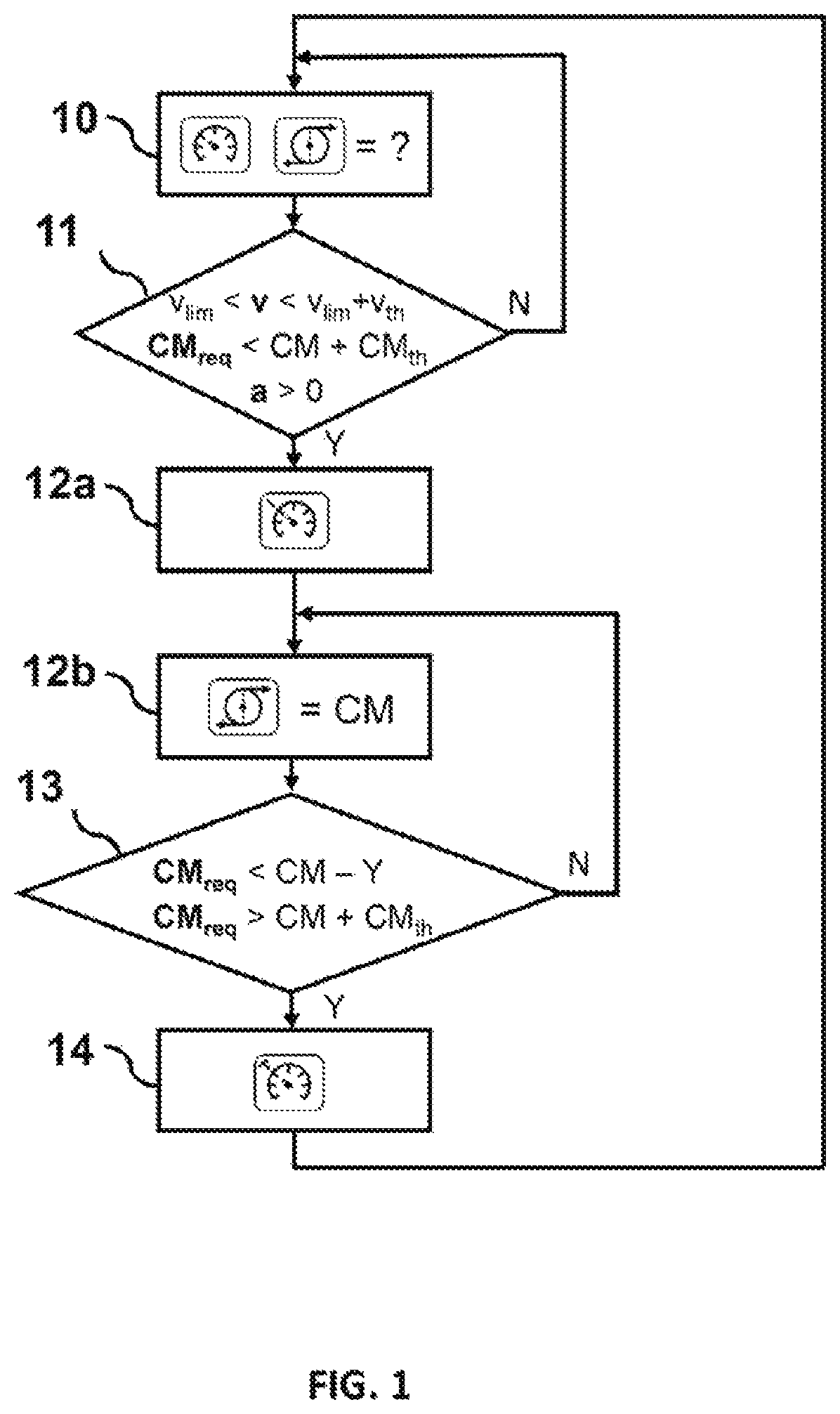
[0041]FIG. 1 shows a diagram of steps of an embodiment of the method for limiting the speed of a motorcycle, more particularly a high-powered motorbike. What is meant by a “high-powered motorbike” is a motorcycle having a high power / weight ratio, for example a two-wheeled vehicle the cylinder capacity of which exceeds 250 cm3, or even 350 cm3. However, the invention is not restricted to these examples.

[0042]The method illustrated in FIG. 1 allows management of the speed limiter, and notably activation or deactivation of same on the basis of precise riding criteria, in the event that a motorcycle speed-limiting mode is already in the active state. Specifically, in the exemplary embodiment described here, the limiter (which means to say the device that in concrete terms applies a speed limit when activated) can be activated only if the motorcycle speed-limiting mode is itself in the active state. One embodiment of the activation and deactivation of the speed-limiting mode will notably...


PUM


Abstract

Disclosed is a solution to the use of a speed limiter in a motorcycle that has a high capacity for acceleration, including a method for limiting the speed of a motorcycle using precise parameters of speed, acceleration and required engine torque and a single control button to manage the smart activation and deactivation of the limiter and to input new speed limits Vlim in a simple way. It thus allows the use of a speed-limiting system in a motorcycle that has a high power / weight ratio by avoiding the sources of interference with the riding and the effects liable to jeopardize its stability.

Description

BACKGROUND OF THE INVENTIONField of the Invention[0001]The present invention relates, in general, to limiting the speed of a motorcycle and, more particularly, to the smart management of the activation / deactivation of a speed limiter and to the implementation of limit speeds in such a speed limiter.[0002]It finds applications in particular in motorcycles of the two-wheel type, having a high power / weight ratio and a high capacity for acceleration. In such applications, the invention makes it possible to improve motorcycle rider safety, while at the same time making the best of their riding experience.Description of the Related Art[0003]The use of speed limiters in motorized vehicles of the automobile type is widespread nowadays. They allow an improvement in the driving comfort and safety of the users of the vehicles equipped therewith. Specifically, when activated, speed limiters make it possible to limit the speed of the vehicle, whatever the acceleration demanded by the driver. In ...

Claims


Application Information

Patent Timeline
Patent Type & Authority Patents(United States)
IPC IPC(8): B60K31/00
CPCB60K31/00B60K2031/0091B60Y2200/12B60Y2300/146B60W30/146B60W2300/36B60W2510/0657B60W2520/10B60W2540/215B60W2552/15
Inventor MOINE, XAVIER
Owner VITESCO TECH GERMANY GMBH
Learn More