
Wire puller lift dolly

a technology of wire pullers and dolly wheels, which is applied in the field of electric cables, can solve the problems of heavy weight of existing wire pullers, high cost, and constraints of existing units, and achieve the effects of reducing unwanted stress, reducing labor intensity, and increasing the quantity of wire to be pulled more quickly

Active Publication Date: 2022-10-04
TRIO ELECTRIC LLC
View PDF3 Cites 0 Cited by
  • Summary
  • Abstract
  • Description
  • Claims
  • Application Information

AI Technical Summary

Benefits of technology

The invention is a device that allows for easier and faster wire pulling on construction sites by alleviating stress caused by a standard wire puller. It also allows for more complex pulls to be made without damage to overhead supports. The device is designed to be mounted vertically, making it easier to set up and use in different locations. It can be attached to an existing wire tugger, making it convenient for users. The device also includes a movable slide frame that allows the wire tugger to be positioned proximate to an overhead wire pull location. Overall, the invention reduces space requirements, allows for faster and larger wire pulls, and makes wire pulling easier and more efficient.

Problems solved by technology

While existing wire-pulling machines such as the one just described may be configured for a different pull situation, existing units have constraints, including high cost, ease of set-up / use due to bulky rigs, and / or jobsite space constraints.
Existing wire pullers are heavy, limiting mobility and operation.
As such, damage to conduit and boxes may occur due to excessive pressure created while pulling a large amount of wire from overhead pull points.
When attempting to pull wire straight down from an overhead electrical box, every wire puller in the current electrical industry applies extreme force that will often result in the box being ripped from the ceiling.
There is little if any flexibility associated with pull-point location, such that the wire, which tends to be very bulky and heavy, must be moved between each pull.
This generally consumes many labor hours and creates numerous safety risks.

Method used


Image

  • Wire puller lift dolly
  • Wire puller lift dolly
  • Wire puller lift dolly

Examples


Embodiment Construction

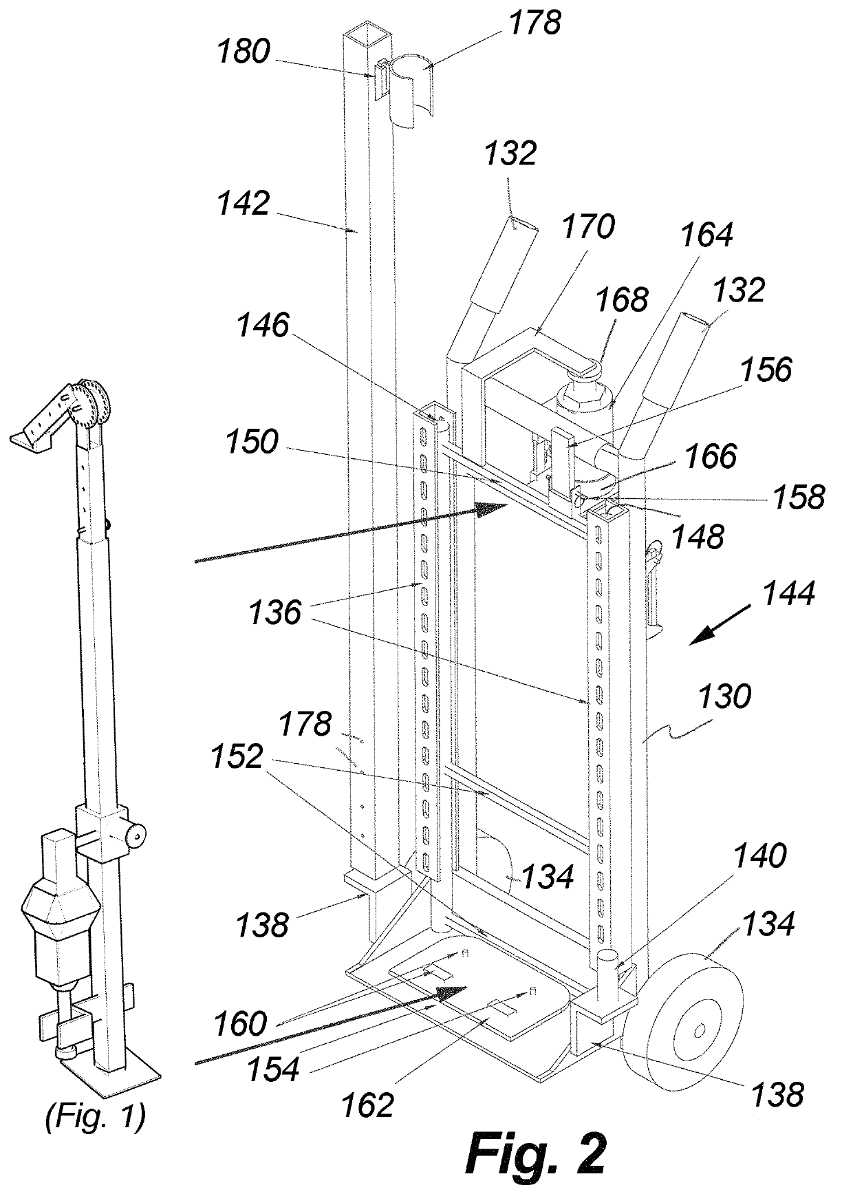
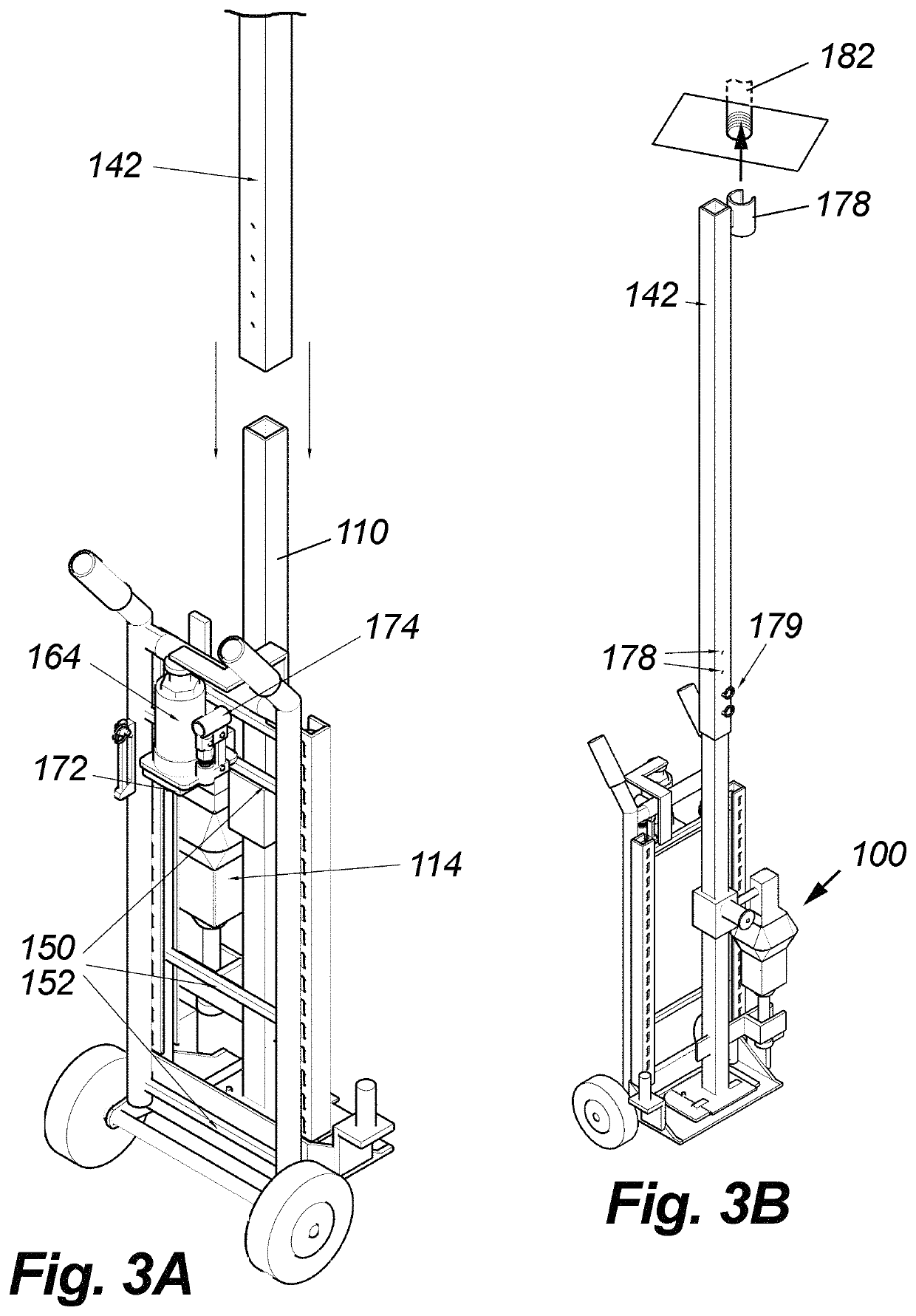
[0016]Having discussed the wire puller of FIG. 1 in the Background of the Invention, the reader's attention is now directed to FIG. 2, which illustrates a preferred embodiment of the invention adapted to receive the wire puller of FIG. 1. The system includes a rigid frame 130 having an upper portion with opposing handles 132 and a lower portion with opposing wheels 134. A pair of opposing slide tube tracks 136 are also rigidly attached to the frame 130. The bottom of the frame includes right and left extension bar mounts 138, each with upwardly extending posts 140. Each mount 138 is configured to removably hold extension bars in an upright orientation. One of the mounts 138 is shown holding extension bar 140, which comprises part of the invention as described below. Either mount may also be used to temporarily hold the elongated arm 106 and upper components of the puller 100, also described below. A spare hitch pin 144 may also be optionally supported on the frame 130.

[0017]The syst...


PUM


Abstract

Apparatus adapted for use with an existing wire tugger includes a primary frame, a slide frame configured to receive the wire tugger, and a jack that causes the slide frame and existing wire tugger to move up and down, thereby enabling a user to position the upper end adapter of the existing wire tugger proximate to an overhead wire pull location. The system enables the existing wire puller to be transported and physically oriented to address a broader range of overhead wire pulling applications on jobsites. A wheeled cart facilitates traversing throughout jobs and vertical wire-puller mounting, thereby mitigating space constraints while allowing for easier set-up and a broader range of uses. Various interchangeable end adapters facilitate temporary coupling and stabilization with respect to different conduit sizes.

Description

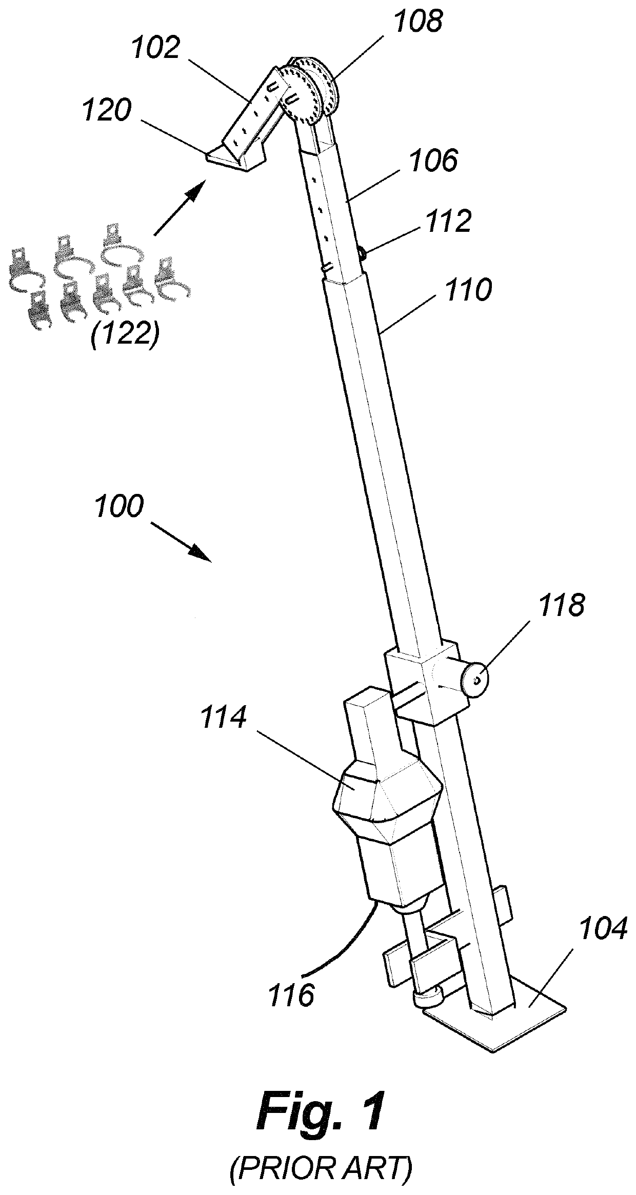
FIELD OF THE INVENTION[0001]This invention relates generally to electrical apparatus and, in particular, to wire pullers. More particularly, the invention is directed to a hand truck or dolly used to transport and lift a wire puller to intended locations, including overhead and ceiling pull points.BACKGROUND OF THE INVENTION[0002]The electrical industry currently has wire-pulling machines and methods in place. FIG. 1 is a drawing that shows an existing, commercially available wire puller or “tugger,” depicted generally at 100. This particular unit is a “3K puller,” so named because it is capable of exerting three thousand pounds of pull force. Other strength pullers are available, including 1K, 3K, 6K, 10K, and so forth, and this invention is not limited in this regard.[0003]The device 100 includes a proximal end 104 that functions as a base, and a distal end 102 that articulates with a rigid, elongated arm 106. The end 102 terminates in an end 120 that is configured to accept vario...

Claims


Application Information

Patent Timeline
Patent Type & Authority Patents(United States)
IPC IPC(8): H02G1/08B66F5/04
CPCH02G1/085B66F5/04
Inventor CARDER, DARRELLPOLLOCK, JARROD
Owner TRIO ELECTRIC LLC
Learn More