
Non-contact power feeding device

a power feeding device and non-contact technology, applied in the direction of transmission, electrical equipment, circuit arrangements, etc., can solve the problems of increasing energy loss associated with power transmission, lowering power transmission efficiency, and affecting the efficiency of power transmission

Active Publication Date: 2022-09-13
ORMON CORP
View PDF17 Cites 0 Cited by
  • Summary
  • Abstract
  • Description
  • Claims
  • Application Information

AI Technical Summary

Benefits of technology

The patent text discusses two techniques for non-contact power feeding. However, each has drawbacks that can result in lower power transmission efficiency and increased energy loss. The technical effect of this patent is to improve the non-contact power feeding technique by addressing these drawbacks and ensuring better power transmission efficiency and energy utilization.

Problems solved by technology

However, in the technique disclosed in Patent Document 1, in a case where communication between the power transmission device and the power reception device cannot be performed for some reason, a non-contact power feeding device may not be able to keep the output voltage from the resonant circuit of the power reception device within a certain range.
As a result, power transmission efficiency is lowered and energy loss associated with the power transmission is increased.

Method used


Image

  • Non-contact power feeding device
  • Non-contact power feeding device
  • Non-contact power feeding device

Examples


Embodiment Construction

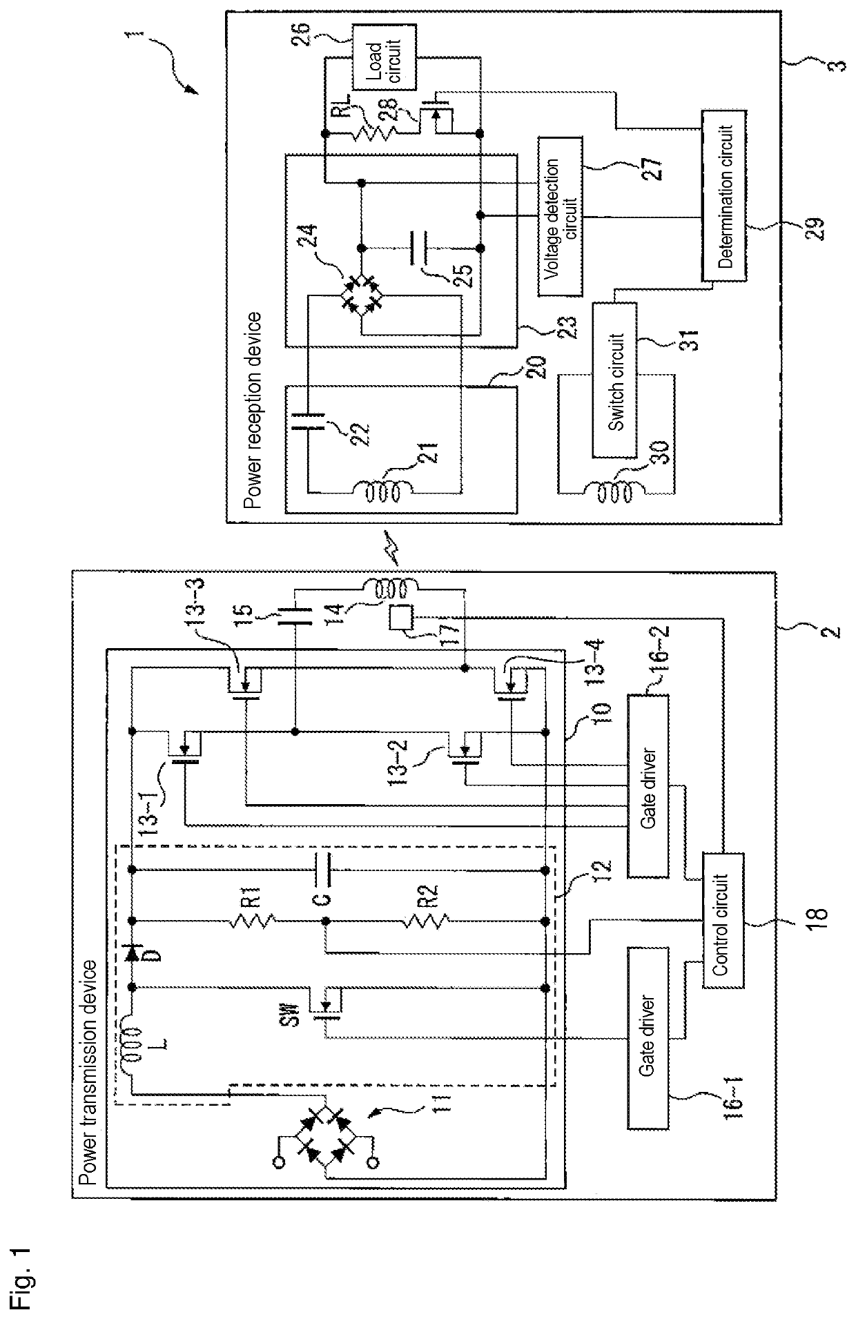
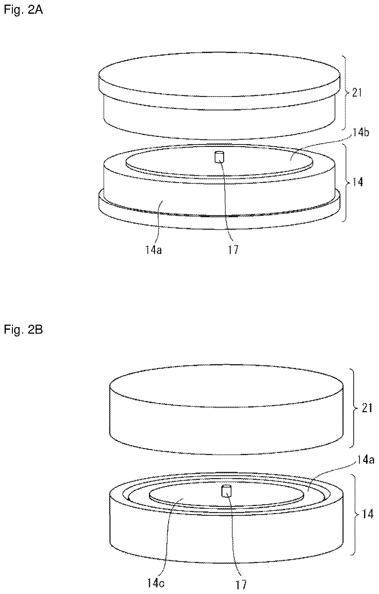
[0034]Hereinafter, a non-contact power feeding device according to one or more embodiments are described with reference to the drawings. In this non-contact power feeding device, a device on a power reception side (hereinafter, simply referred to as a power reception device) has: a reception coil for power reception; and a coil for resonance suppression (hereinafter, simply referred to as a resonance suppression coil) provided to be capable of being electromagnetically coupled to the reception coil. Then, when an output voltage from a resonant circuit including the reception coil becomes equal to or larger than a predetermined threshold value, the power reception device short-circuits the resonance suppression coil and changes a resonance condition of the resonant circuit. Whereas, a device on a power transmission side (hereinafter, simply referred to as a power transmission device) has a magnetic field detection element configured to detect a strength of a magnetic field according ...


PUM


Abstract

A power transmission device of a non-contact power feeding device according one or more embodiments may include a control circuit configured to control at least one of a switching frequency or a voltage of AC power supplied from a power supply circuit to a transmission coil, on the basis of a change over time in a strength of a magnetic field detected by a magnetic field detection element configured to detect a strength of a magnetic field generated from the transmission coil of the power transmission device. Whereas, a power reception device has a resonant circuit having a reception coil configured to receive electric power from the power transmission device and a resonance suppression coil arranged to be capable of being electromagnetically coupled to the reception coil.

Description

TECHNICAL FIELD[0001]The present invention relates to a non-contact power feeding device.BACKGROUND ART[0002]Conventionally, there has been studied so-called non-contact power feeding (also called wireless power feeding) technology, in which electric power is transmitted through space without using a metal contact point or the like.[0003]In a power feeding device using non-contact power supply technology (hereinafter, simply referred to as a non-contact power feeding device), when a positional relationship between a coil on a primary side (a power transmission side) and a coil on a secondary side (a power reception side) fluctuates, a coupling degree between the two coils changes. As a result, an output voltage from a device of the power reception side to a load circuit also fluctuates. Therefore, a technique for keeping the output voltage constant has been proposed (see, for example, Patent Documents 1 and 2).[0004]For example, Patent Document 1 proposes transmitting, by a power re...

Claims


Application Information

Patent Timeline
Patent Type & Authority Patents(United States)
IPC IPC(8): H02J50/12H04B5/00
CPCH02J50/12H04B5/0037H04B5/0081H02J50/005H04B5/26H04B5/79
Inventor NAKAO, GOROKAWAI, YUSUKETABATA, KENICHINOMURA, ATSUSHITAKEYAMA, TAKAHIRONAKAJO, MASANOBU
Owner ORMON CORP
Learn More