
Lock for a motor vehicle

a technology for motor vehicles and locks, applied in the field of locks for motor vehicles, can solve problems such as new problems in developmen

Active Publication Date: 2022-08-16
KIEKERT AG
View PDF13 Cites 3 Cited by
  • Summary
  • Abstract
  • Description
  • Claims
  • Application Information

AI Technical Summary

Benefits of technology

The technical effect of this patent is to develop a motor vehicle lock that provides enough lift for quick lowering and also provides enough force to close the lock against the force of a seal. Additionally, the invention provides a simple and cost-effective locking system.

Problems solved by technology

The structural complexity of the closure and the new requirements in relation to overcoming sealing pressure pose new problems in terms of development.

Method used


Image

  • Lock for a motor vehicle
  • Lock for a motor vehicle

Examples


Embodiment Construction

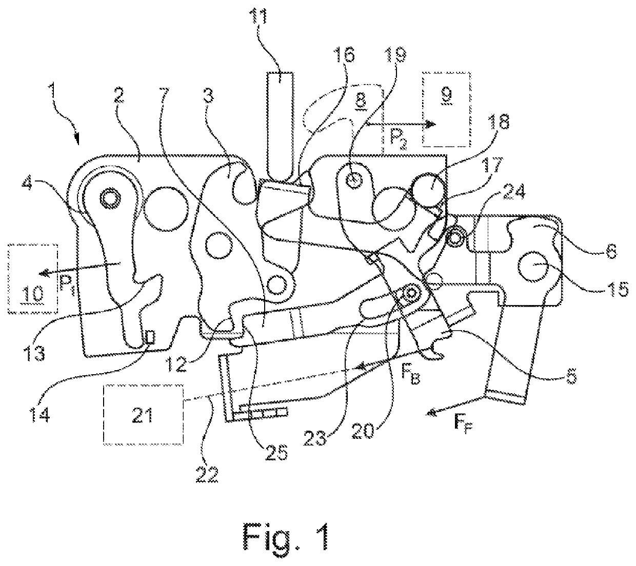
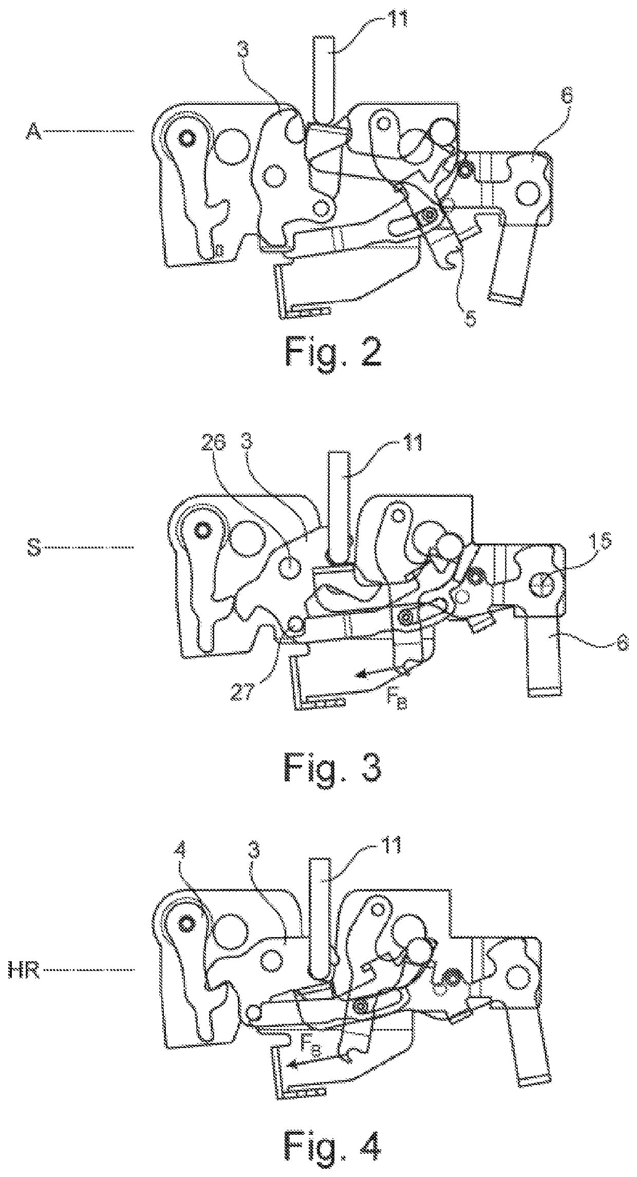
[0043]FIG. 3 shows the secured position S. The drive lever 5 has been pivoted in the clockwise direction by the closure drive 21 and in particular by the Bowden cable 22. By means of the pivoting movement, the ejector 6 has pivoted about its shaft 15 in the counter-clockwise direction, so that the lock holder 11, and in particular the lock holder 11 in combination with a load from a bonnet, moves into the secured position S. At the same time, the pivoting movement of the ejector 6 causes the rotary latch 3 to have pivoted about the shaft 26 in the clockwise direction through the lock holder 11, so that a cylinder pin 27 enters the engagement region of the recess 25 in the closure lever 7. In this secured position S, the rotary latch 3 comes into interlocking engagement with the lock holder 11 and the closure lever 7 comes into engagement with the pin 27. At the same time, the pin 20 reaches the end of the guide groove 23, as a result of which the guide pin 20 is capable of transferr...


PUM


Abstract

A method and a locking device for a motor vehicle, in particular a bonnet lock, having a locking mechanism with a rotary latch and at least one pawl, a locking pin and an ejector interacting with the locking pin, wherein the locking pin can be brought into a lifting-off position by means of the ejector, and with at least one electrically actuable means for moving the lock holder from the lifting-off position into a locking position, wherein a drive lever is provided, and wherein the ejector and, at least indirectly, the rotary latch are actuable by means of the drive lever.

Description

FIELD OF DISCLOSURE[0001]The invention relates to a lock for a motor vehicle, in particular a bonnet lock, having a locking mechanism with a rotary latch and at least one pawl, a locking pin and an ejector interacting with the locking pin, wherein the locking pin can be brought into a lifting-off position by means of the ejector, and with at least one electrically actuable means for moving the lock holder from the lifting-off position into a locking position.BACKGROUND OF DISCLOSURE[0002]Locks or locking systems for motor vehicles are used where doors, hatches or movable components on motor vehicles need to be retained in order to ensure that the motor vehicle can be safely driven. The locking systems serve primarily to retain the movable components in the locked position thereof, and so an increasing number of convenience functions are coming to the fore nowadays. In this sense, for example, doors, hatches or bonnets may be electrically actuated during the opening and / or closing pr...

Claims


Application Information

Patent Timeline
IPC IPC(8): E05B81/20E05B81/16E05B85/26E05B83/24E05B79/20
CPCE05B81/20E05B79/20E05B81/16E05B83/24E05B85/26E05Y2900/536E05B81/14
Inventor STURM, CHRISTIAN
Owner KIEKERT AG
Learn More