Propulsion device

a technology of propulsion device and propellant, which is applied in the direction of machines/engines, mechanical equipment, transportation and packaging, etc., to achieve the effect of being cheap to manufactur

Active Publication Date: 2016-07-19
NOUROLLAH MAHMOUD
View PDF20 Cites 1 Cited by
  • Summary
  • Abstract
  • Description
  • Claims
  • Application Information

AI Technical Summary

Benefits of technology

[0015]Still another object of this invention is to provide a propulsion device, which is inexpensive to manufacture.
[0016]Still further, an object of this

Problems solved by technology

Regardless of the different designs, there is constant effort

Method used


Image

  • Propulsion device
  • Propulsion device
  • Propulsion device

Examples


first embodiment

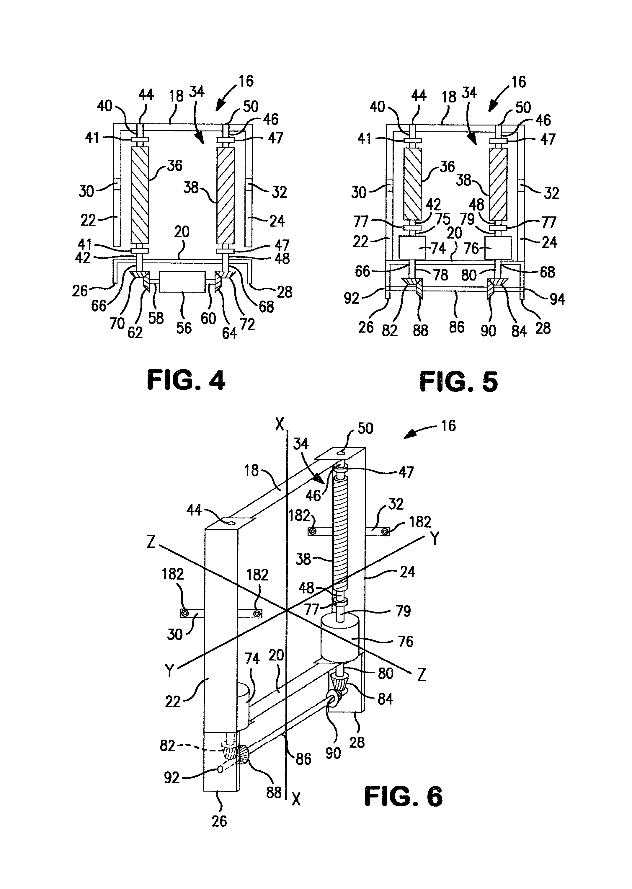
[0092]Referring now to FIG. 22, an alternative embodiment of a propulsion device 10′ is shown. The propulsion device 10′ will be described using similar numbers for the common parts which match those described above for the The propulsion device 10′ includes a frame 16 having a side member 22 and a side member 24, only one side member 22 being visible in FIG. 22, and a pair of support arms 30 and 32 secured to the side members 22 and 24 which are aligned parallel to one another. The propulsion device 10′ also has a first mechanism 34 secured to the frame 16 which can provide linear motion to a device interacting therewith. The propulsion device 10′ further includes a drive mechanism 56 which is capable of rotating the first mechanism 34. The drive mechanism 56 includes a first motor 74 and a second motor 76. The first and second motors, 74 and 76 respectively, can be identical to one another. The first and second motors, 74 and 76 respectively, can be electrical motors, gasoline mo...

second embodiment

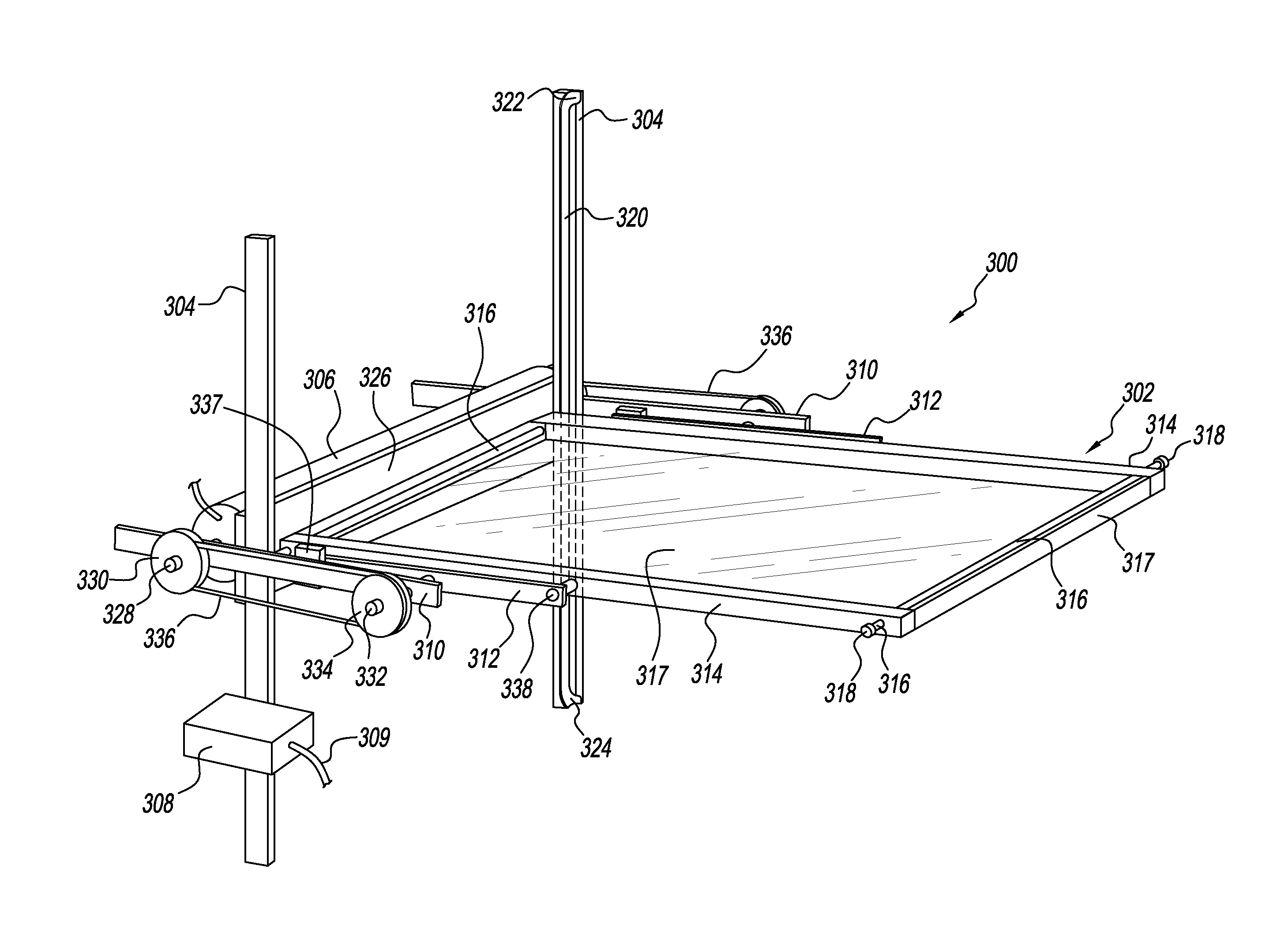
[0118]With reference to FIGS. 33-38, the propulsion device 300 includes a wing 302, a pair of sliding rails 304, an electric motor 306, an electrical power source 308, a pair of connecting rod supports 310 and a pair of connecting rods 312. Each wing 302 includes two lengthwise members 314, two cross rods 316, an outer layer 317 and four roller bearings 318. One end of the two cross rods 316 are pressed into each end of one of the two lengthwise members 314, such that the one end of the two cross rods 316 extends past the an outer surface of the lengthwise member 314. The other end of the two cross rods 316 are pressed into each end of the other one of the two lengthwise members 314, such that the other end of the cross rods 316 extends past the outer surface of the lengthwise member 314. Each end of the two cross rods 316 is terminated with the four roller bearings 318. The outer layer 317 is secured around a top and bottom of the two lengthwise members 314 and the two cross rods 3...


PUM


Abstract

A propulsion device preferably includes a wing, a pair of sliding rails, an electric motor, an electrical power source, a pair of connecting rod supports and a pair of connecting rods. Each wing includes two lengthwise members, two cross rods, an outer layer and four roller bearings. Each sliding rail includes a lengthwise track formed on an inner surface thereof. Each end of a cross plate is attached to one of the pair of sliding rails. The electric motor is attached to the cross plate. The electrical power source is connected to the electric motor. The electrical power source is preferably secured to one of the pair of sliding rails. One end of connecting rod support is attached to one of the pair of sliding rails.

Description

CROSS-REFERENCES TO RELATED APPLICATIONS[0001]This is a continuation-in-part patent claiming the benefit of application Ser. No. 13 / 661,137 filed on Oct. 26, 2012.BACKGROUND OF THE INVENTION[0002]1. Field of the Invention[0003]This invention relates to a propulsion device, which is capable of lifting and / or propelling a person, an aircraft or an object, such as a helicopter, an airplane or package, through the air.[0004]2. Discussion of the Prior Art[0005]Today, there are numerous vertical take-off and propulsion mechanisms. Some are relatively small and are designed to be strapped onto a person's back while others are larger and can be used to power an aircraft, such as a helicopter or an airplane. A small power pack used to lift a person is sometimes referred to as a jetpack. Jetpacks usually include some kind of motor or engine, which can utilize air velocity or water velocity to lift and propel a person through the air. Some propulsion mechanisms can utilize a power driven shaft...

Claims


Application Information

Patent Timeline
IPC IPC(8): B64C11/00B64C39/00B64C39/02F01D23/00B63H1/04
CPCB64C11/00F01D23/00B64C39/003B64C39/026B63H1/04B64C27/00B64C39/006B63B34/15
Inventor NOUROLLAH, MAHMOUD
Owner NOUROLLAH MAHMOUD
Why Eureka
Try Eureka