
Chain saw

a chain saw and chain saw technology, applied in the field of power tools, can solve the problems of chain saw service life reduction, production efficiency reduction, and housing breakag

Active Publication Date: 2022-08-16
GLOBE (JIANGSU) CO LTD
View PDF61 Cites 1 Cited by
  • Summary
  • Abstract
  • Description
  • Claims
  • Application Information

AI Technical Summary

Benefits of technology

The present invention is a chain saw with a simple structure that is safe, comfortable and easy to use. It is also cost-effective and convenient for production and installation. The chain saw has been designed to ensure mechanical strength while in use. Its stable operation and service life are improved. The chain saw has been optimized to fix and connect the front handle to the housing, which simplifies the assembly process and reduces production and assembly costs. It has also been designed with an improved load-bearing strength and reduced manufacturing costs. Additionally, the design of the discharge port prevents the entry of sawdust which prevents braking failure and running jam of the chain saw.

Problems solved by technology

However, the front handle is only designed based on improving the comfortability when grasped by the operator and reducing the fatigue of long-term operating the chain saw.
However, these designed front handles often cause the break of the housing when the chain saw are accidentally dropped.
Meanwhile the production efficiency is reduced because the housing is flipped many times during production and assembly.
In addition, when a protective plate of the chain saw is rotated, the debris generated by the chainsaw enter inside of the chainsaw to threaten the operation of the internal brake and the transmission structure and then the service life of the chain saw is reduced.

Method used


Image

  • Chain saw
  • Chain saw
  • Chain saw

Examples


first embodiment

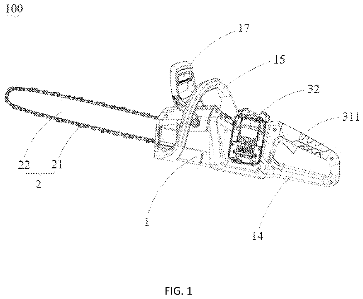
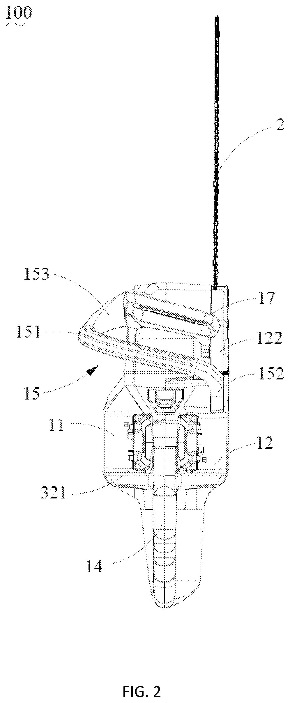
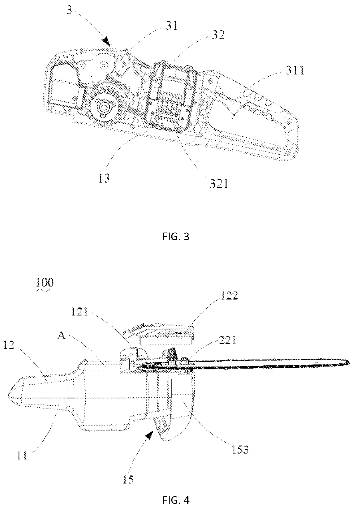
[0040]FIG. 1 to FIG. 4 depict a chain saw 100 according to the present invention. The chain saw 100 includes a housing 1, a cutter 2 mounted on the housing 1 and a power assembly 3 received in the housing 1 for driving the cutter 2.

[0041]The housing 1 has a front end for fixedly connecting a cutter 2 and a rear end away from the cutter 2. The housing 1 has a longitudinally extending shaft, which defines the direction from the rear end to the cutter as a positive direction. The housing 1 includes a first housing 11 and a second housing 12 both extending along the positive direction. The first housing 11 and the second housing 12 are respectively located at two opposite sides of the housing 1. A receiving cavity 13 is formed by the first and second housings 11, 12. The first and second housings 11, 12 are interlocked with each other. The second housing 12 has a mounting groove 121 depressed from a side wall A thereof toward the first housing 11 and a mounting portion 122 detachably mo...

fourth embodiment

[0064]FIG. 9 to FIG. 13 depict a chain saw 100 according to the present invention. Please refer to FIG. 9 and FIG. 10, the chain saw 100 includes a housing 1, a handle provided on the housing 1, and a protective plate 17. The housing 1 is provided with an outlet opening 44 to discharge the sawdust brought inside the chain saw 100 when cutting to the outside of the housing 1, so that it is difficult for the sawdust to accumulate inside the chain saw 1, which improves the reliability of the chain saw 100 when braking, and further improves the using safety of the chain saw 100.

[0065]Specifically, in this embodiment, the chain saw 100 further includes a battery pack 6 to provide energy for the chain saw 100. In other embodiments, the chain saw 100 can also be connected to an external power source, an internal combustion engine, etc. The protective plate 17 is arranged at a distance from the front handle 15 and on a side of the front handle 15 away from the rear handle 14. The chain saw ...


PUM


Abstract

A chain saw includes a housing, the housing including a first housing, a second housing, and a receiving cavity formed by the first housing and the second housing; a cutter including a blade chain and a blade bar for supporting the blade chain, the cutter being mounted on the housing; a power assembly, the power assembly including a drive unit for driving the cutter and a power supply unit for supplying power to the drive unit; a front handle connected to the second housing and surrounding the first housing, the front handle including a grip portion, a first and second fixing parts which are located at two ends of the grip portion, the first fixing part abutting on the side wall of the second housing, and the second fixing part being located at the bottom of the housing and connecting with the second housing.

Description

CROSS-REFERENCE TO RELATED APPLICATIONS[0001]This application is a US application which claims the priority of CN Application Serial No. 201921748973.8, filed on Oct. 18, 2019, the disclosures of which are hereby incorporated by reference in their entirety.TECHNICAL FIELD[0002]The present invention relates to a power tool, in particular to an electrically powered chain saw.BACKGROUND[0003]Chain saw is powered by gasoline, electricity or hydraulics and mainly used for cutting. The chain saw has two handles respectively located at two opposite ends of a housing thereof. One handle is located at a rear end of the housing and provided with a trigger thereon. The other handle is located at a front end of the housing. The stability of the chainsaw can be ensured through the front handle grasped by one hand of the operator to control the working direction and the rear handle grasped by the other hand of the operator during operation.[0004]However, the front handle is only designed based on...

Claims


Application Information

Patent Timeline
Patent Type & Authority Patents(United States)
IPC IPC(8): B27B17/00
CPCB27B17/0008B27B17/02B27B17/083B27G19/003B27B17/00B23D59/006
Inventor ZHANG, LINGAOLI, JINGSHANZONG, ZHIWEIREN, LIANZHI
Owner GLOBE (JIANGSU) CO LTD
Learn More