
Multi-axially braided reinforcement sleeve for concrete columns and method for constructing concrete columns

a technology of reinforcement sleeves and concrete, applied in the direction of forming/shuttering/falseworks, building components, building parts, etc., can solve the problems of low tensile strength of concrete, easy cracking and breaking, and disadvantages of using concrete to construct columns

Active Publication Date: 2022-08-09
LOW RAYMOND ALAN
View PDF40 Cites 0 Cited by
  • Summary
  • Abstract
  • Description
  • Claims
  • Application Information

AI Technical Summary

Benefits of technology

The multi-axially braided reinforcement sleeve reduces construction costs and time, enhances structural integrity by eliminating rebar-related failures, and improves safety by eliminating formwork-related hazards, while providing uniform concrete filling and resistance to earthquake damage.

Problems solved by technology

However, there are some disadvantages to using concrete to construct columns.
One disadvantage is concrete's low tensile strength.
For example, if a column were to be made solely of concrete, it would crack and break relatively easily when subjected to tensile axial forces.
However, unusual stresses from a catastrophic event such as an earthquake can cause shaking motions that can damage the concrete in the column, and eventually lead to structural failure.
For example, an earthquake can pulverize the concrete in a column, and with nothing to contain it, the pulverized concrete pieces fall out, causing the entire column to fail, which in turn can bring down an entire building, or at least portions of it.
Another disadvantage of rebar-reinforced concrete columns is their construction cost, which can be substantial.
Although sometimes formwork can be reused during the scope of a project, the ability to reuse it is limited.
Still another disadvantage is that rebar is heavy and can be expensive to transport, especially the pre-formed structures.
The conventional multi-step column construction technique described above using rebar, formwork, and frames, adds significant labor and material costs to the total construction cost of a building.
Unfortunately it also creates a number of additional construction and practical problems such as: concrete honeycombing in the formwork; cold joints; bug holes; cracking concrete during form removal; over-vibration possibly causing formwork blowout; improper or insufficient ties being used; formwork failures; improper construction due to workers' lack of attention to formwork details; possible removal of formwork too early; the extensive time needed to plan for formwork and generating a realistic schedule and stripping time requirements; determining the capacity of equipment available to handle form sections and materials; determining the capacity of mixing and placing equipment; creating consistently strong construction joints; determining suitability for reuse of forms as affected by stripping time; considering the relative merits of job-built, shop-built and ready-made forms; and weather-related problems (such as rain or snow) that can adversely affect the formwork.
Not only does rebar add to cost, but it is believed that the properties of the rebar itself can contribute to the destruction of the column during an earthquake since the column is subject to alternating compression and tension as the earthquake waves pass through.
The alternating compression and tension tend to eject and pulverize the concrete around the rebar, undermining the structure of the column and possibly leading to ultimate failure and subsequent collapse.

Method used


Image

  • Multi-axially braided reinforcement sleeve for concrete columns and method for constructing concrete columns
  • Multi-axially braided reinforcement sleeve for concrete columns and method for constructing concrete columns
  • Multi-axially braided reinforcement sleeve for concrete columns and method for constructing concrete columns

Examples


Embodiment Construction

Terms

[0035]As used herein, the term “concrete”, or “concrete aggregate” includes cement in various combinations with water, sand, gravel, rocks, and other materials that help to add to its strength in the particular conditions in which the concrete will be employed. For ease of reference, the term “concrete” as used herein includes any of these combinations of cement and other materials.

[0036]For purposes herein, concrete can be defined as including a cement paste, a coarse aggregate, and other materials such as sand. The term “coarse aggregate” includes larger solids, like rock and gravel. The term “cement paste” includes water mixed with cement. When fresh, cement paste typically flows in a semi-liquid manner.

Multi-Axial Braided Reinforcement Sleeve

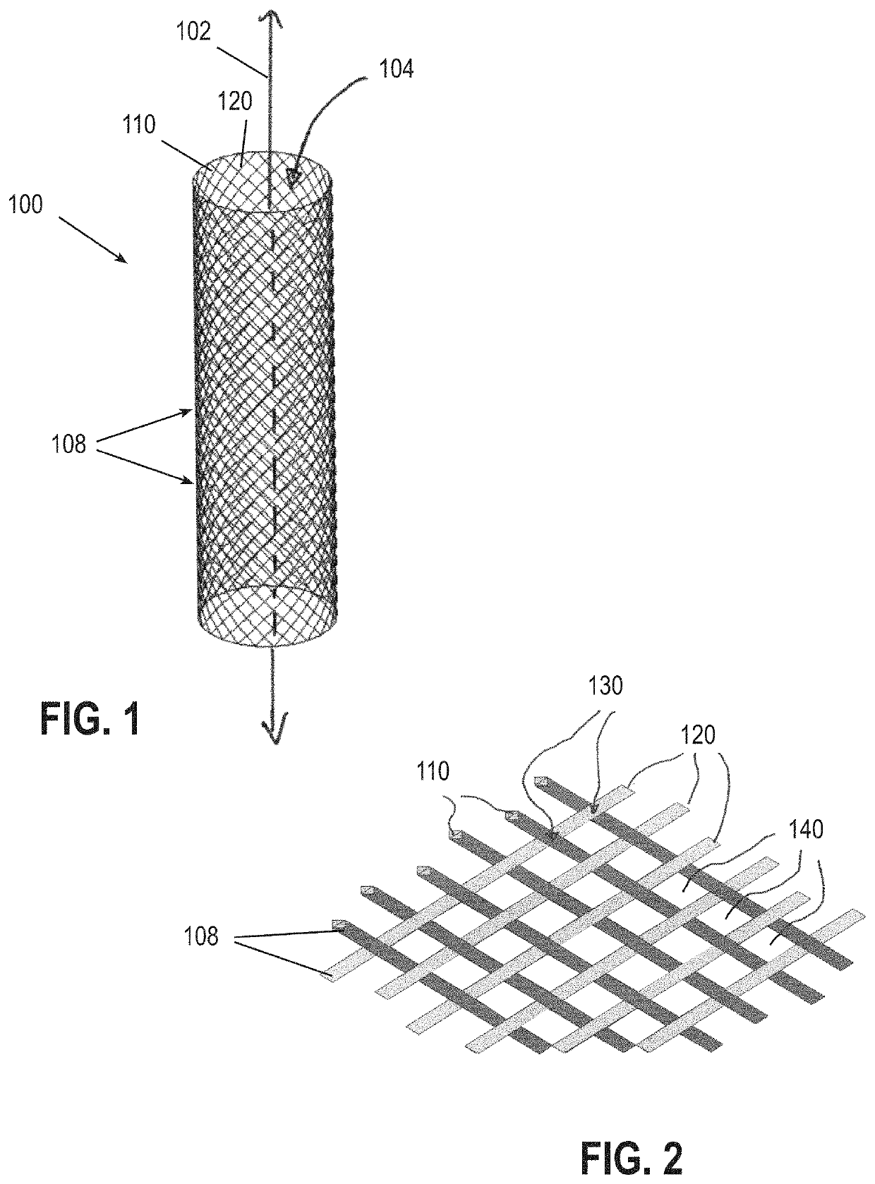
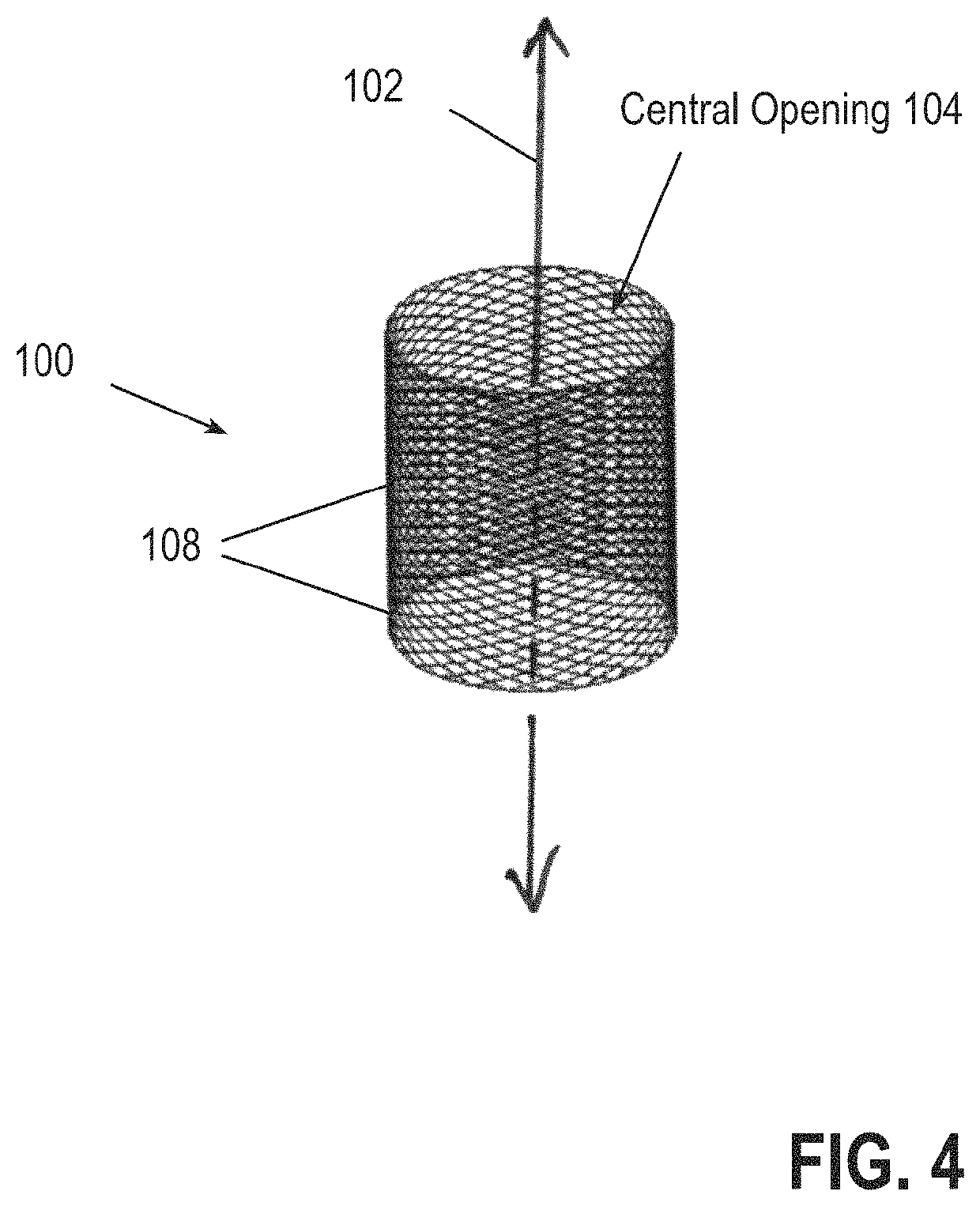
[0037]Reference is first made to FIGS. 1 and 2. FIG. 1 is a perspective view of a multi-axially braided reinforcement sleeve 100 in an extended configuration; FIG. 2 is a perspective closeup view of a cut-out portion of the biaxially br...


PUM

PropertyMeasurementUnit
sizeaaaaaaaaaa
flexibleaaaaaaaaaa
lengthaaaaaaaaaa

Abstract

A multi-axially braided reinforcement sleeve that provides a low cost, simpler method to form strong concrete columns for constructing buildings and other structures. The braided reinforcement sleeve provides structural support and the rebar normally embedded to provide structural support in concrete can be eliminated, preventing the possibility of rebar oxidation which might otherwise undermine the structural integrity of the column. The reinforcement sleeve is lightweight, easy to transport, and can be greatly reduced in size to facilitate transportation. The reinforcement sleeve and construction method can be utilized in many implementations, and can be particularly useful for constructing buildings or other structures in geographic areas that are subject to earthquakes and where low cost is important.

Description

CROSS-REFERENCE TO RELATED APPLICATION[0001]Reference is made, and priority is hereby claimed to U.S. Provisional Patent Application No. 62 / 888,854, filed Aug. 19, 2019, entitled MULTI-AXIALLY BRAIDED REINFORCEMENT SLEEVE FOR CONCRETE COLUMNS AND METHOD FOR CONSTRUCTING CONCRETE COLUMNS, which is incorporated herein by reference.BACKGROUND1. Field of the Invention[0002]The invention relates to materials, components, and construction techniques for forming vertical support structures using concrete aggregate.2. Description of Related Art[0003]A fundamental and critical element of building construction is the vertical support structure that holds up the beams, roofs, and other parts of a building. One type of vertical support structure is a column, which is a strong, approximately cylindrical structure that can, for example, extend from floor to ceiling inside a structure, or outside, from the ground up to the first, second or subsequent floors. Each column is designed with the streng...

Claims


Application Information

Patent Timeline
Patent Type & Authority Patents(United States)
IPC IPC(8): E04C5/06E04C3/34E04G13/02E04G9/08E04C5/07
CPCE04C5/0609E04C3/34E04C5/07E04G9/08E04G13/021E04C3/30E04C3/36E04C5/012E04C5/0618
Inventor LOW, RAYMOND ALAN
Owner LOW RAYMOND ALAN
Learn More