Surface acoustic wave device

a surface acoustic wave and resonator technology, applied in the direction of impedence networks, electrical devices, etc., can solve the problems of difficult manufacture, too large loss,

Active Publication Date: 2022-08-02
NDK SAW DEVICES CO LTD
View PDF7 Cites 0 Cited by
  • Summary
  • Abstract
  • Description
  • Claims
  • Application Information

AI Technical Summary

Benefits of technology

[0003]Recent development of mobile communication systems, such as a mobile phone, increases requests for a SAW filter that has a narrow band and a steep attenuation characteristic. Therefore, there has been reported various methods for improving obtaining satisfactory values of an electromechanical coupling coefficient k2 and Temperature Coefficients of Frequency (TCF) as an indicator of a frequency versus temperature characteristic. As the improving method, there has been reported that the SAW filter is configured using a substrate where a piezoelectric substrate having a thickness about a wavelength and a high-acoustic-velocity substrate are laminated. Such a method using the laminated substrate has been known also as a method for improving characteristics of, not only the SAW filter, but other surface acoustic wave devices such as a SAW resonator.

Problems solved by technology

However, thus reported LLSAW resonator has the Q factor of around 1000 in an 800 MHz band, and a problem arises in that a loss is too significant to use this LLSAW resonator as a practical device.
In addition, a problem arises in that a small film thickness of the electrode in the above-described LLSAW resonator fails to provide a sufficient reflection characteristic of the device.
Further, a problem arises in that a thin thickness of the LiTaO3 substrate makes manufacture difficult.

Method used


Image

  • Surface acoustic wave device
  • Surface acoustic wave device
  • Surface acoustic wave device

Examples


Embodiment Construction

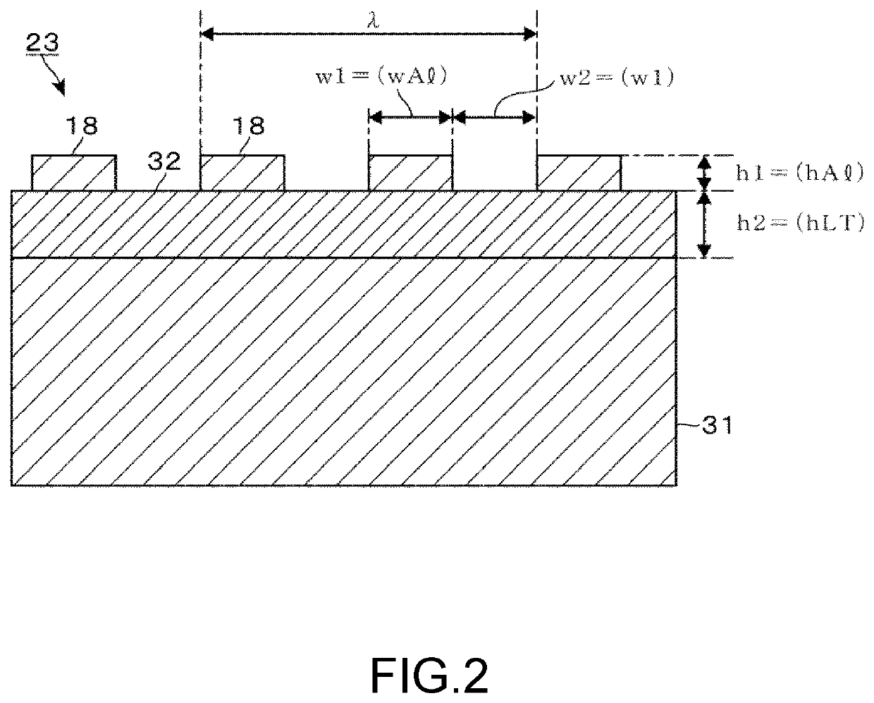
[0024]FIG. 1 illustrates a ladder-type filter 10 where a plurality of SAW (surface acoustic wave) resonators 1 are combined in a ladder-type, as one embodiment of a surface acoustic wave device of the disclosure. In this ladder-type filter 10, three SAW resonators 1 are each disposed between an input port 11 and an output port 12 in series as a series arm, while one SAW resonator 1 is connected to those SAW resonators 1, 1 in parallel as a parallel arm. Each SAW resonator 1 is simply illustrated. A reference numeral 13 in the drawing denotes a ground port. A reference numeral 14 in the drawing denotes a routing electrode that electrically connects the SAW resonators 1, 1 one another or electrically connects the SAW resonator 1 to the ports 11, 12, and 13.

[0025]The SAW resonator 1 includes an Inter Digital Transducer (IDT) 15 and reflectors 16, 16 formed on both sides of this IDT 15 in a propagation direction of a surface acoustic wave (hereinafter referred to as “elastic wave”). The...


PUM


Abstract

A surface acoustic wave device includes a quartz layer, a piezoelectric layer, and an Inter Digital Transducer. A rotation in a right-screw direction is assumed as a +-rotation. A three-dimensional coordinate system formed by an x1-axis, a y1-axis, and a z1-axis respectively matching an X-axis, a Y-axis, and a Z-axis as crystallographic axes of a quartz-crystal is rotated from +125.25° in a range of ±3° with the x1-axis as a rotation axis. Subsequently, the three-dimensional coordinate system is rotated from +45° in a range of ±2° with the z1-axis as the rotation axis. Subsequently, the three-dimensional coordinate system is rotated from −45° in a range of ±2° with the x1-axis as the rotation axis. The quartz layer is cut along a surface as a sectional plane perpendicular to the z1-axis. The quartz layer has a propagation direction of the surface acoustic wave in a direction parallel to the x1-axis.

Description

CROSS-REFERENCE TO RELATED APPLICATIONS[0001]This application is based on and claims priority under 35 U.S.C. § 119 to Japanese Patent Application No. 2018-027225, filed on Feb. 19, 2018, and the entire content of which is incorporated herein by reference.TECHNICAL FIELD[0002]This disclosure relates to a surface acoustic wave device that uses a surface acoustic wave (SAW).DESCRIPTION OF THE RELATED ART[0003]Recent development of mobile communication systems, such as a mobile phone, increases requests for a SAW filter that has a narrow band and a steep attenuation characteristic. Therefore, there has been reported various methods for improving obtaining satisfactory values of an electromechanical coupling coefficient k2 and Temperature Coefficients of Frequency (TCF) as an indicator of a frequency versus temperature characteristic. As the improving method, there has been reported that the SAW filter is configured using a substrate where a piezoelectric substrate having a thickness ab...

Claims


Application Information

Patent Timeline
Patent Type & Authority Patents(United States)
IPC IPC(8): H03H9/02H03H9/64H03H9/145
CPCH03H9/02551H03H9/02559H03H9/02574H03H9/02992H03H9/14538H03H9/6483H03H9/6423H03H9/6413
Inventor HIRATSUKA, YUYAHIROTA, KAZUHIRO
Owner NDK SAW DEVICES CO LTD
Why Eureka
Try Eureka