
Scanning mirror having balancing body, and method for balancing a scanning mirror

Active Publication Date: 2022-08-02
SCANLAB GMBH
View PDF16 Cites 0 Cited by
  • Summary
  • Abstract
  • Description
  • Claims
  • Application Information

AI Technical Summary

Benefits of technology

The patent is about a scanning mirror used in laser systems. The invention includes a balancing system that uses multiple recesses on the same side of the mirror to hold the balancing mass. This allows for quick and cost-effective balancing without the need for complex processes and saving manufacturing costs. The balanced mirror also has a flat surface and is optimized for inertia. Additionally, the patent suggests measuring the imbalance of the mirror again after the balancing process is complete to confirm if the problem still exists.

Problems solved by technology

A thread can be introduced into these materials only with the greatest amount of effort.
The flatness of the mirror surface can be adversely affected by large or unfavorably positioned recesses in the rear face or the lateral faces of the mirror body or in the mirror body itself.
It is disadvantageous in this case that the thread is extremely complex to produce, whereby the manufacturing costs of the scanning mirror are considerably increased.
Moreover, the method for balancing the scanning mirror is highly complex, since a plurality of iterative steps is required in order to be able to determine the optimal distance of the screws from the central axis.

Method used


Image

  • Scanning mirror having balancing body, and method for balancing a scanning mirror
  • Scanning mirror having balancing body, and method for balancing a scanning mirror
  • Scanning mirror having balancing body, and method for balancing a scanning mirror

Examples


Embodiment Construction

[0042]Reference will now be made to embodiments of the invention, one or more examples of which are shown in the drawings. Each embodiment is provided by way of explanation of the invention, and not as a limitation of the invention. For example features illustrated or described as part of one embodiment can be combined with another embodiment to yield still another embodiment. It is intended that the present invention include these and other modifications and variations to the embodiments described herein.

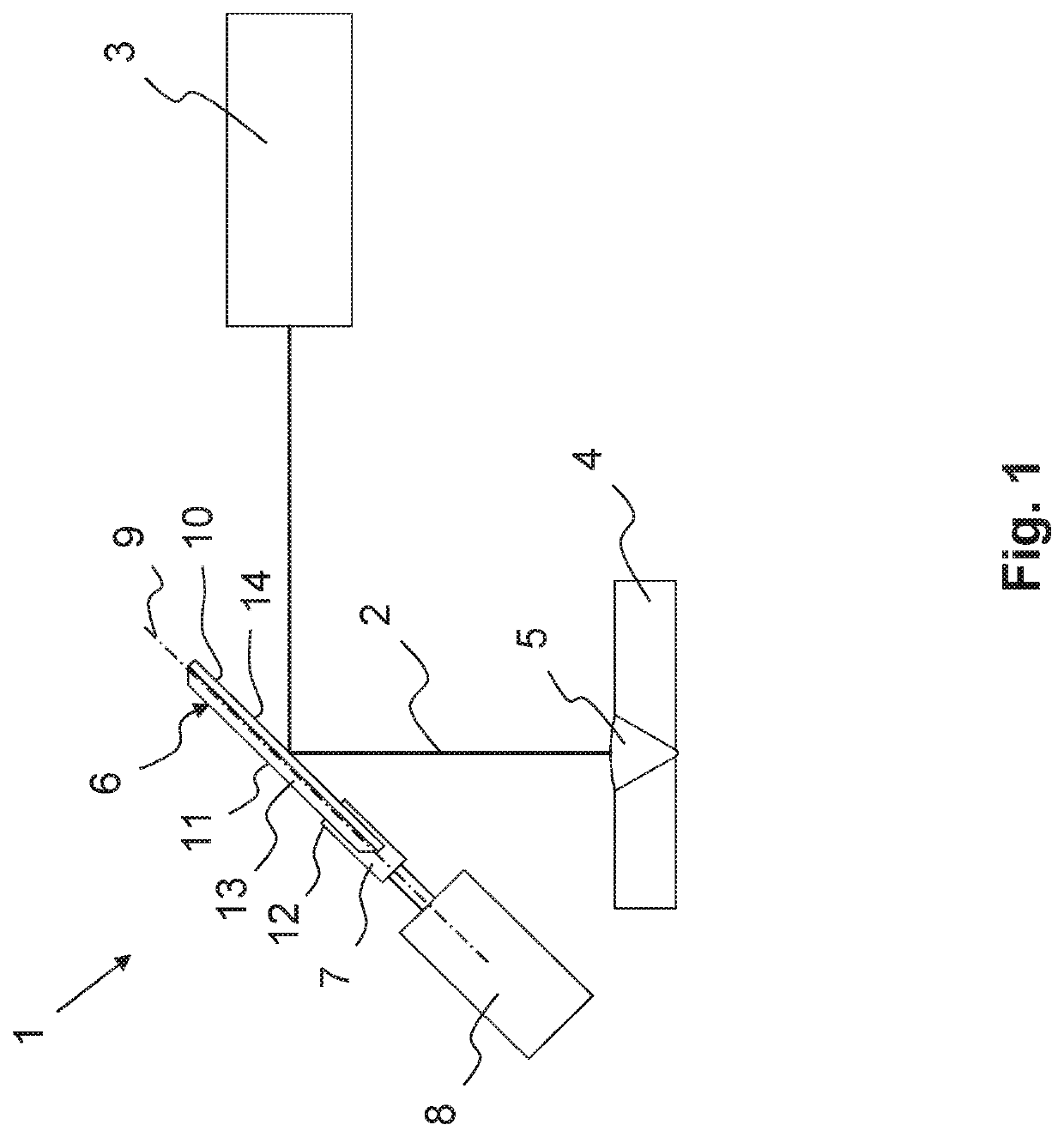
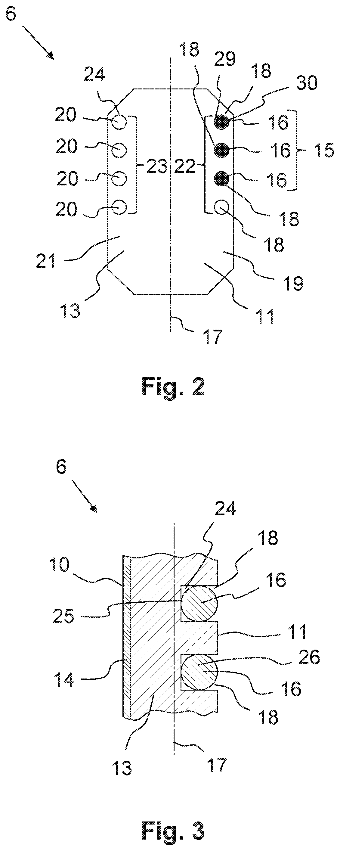
[0043]FIG. 1 shows a section of a laser scanning system 1, with the aid of which a laser beam 2 of a laser 3 can be deflected. The laser beam 2 is utilized, in this case, for forming a weld 5 on a workpiece 4. The laser beam 2 is emitted from the laser 3 and is deflected onto the workpiece 4 by a scanning mirror 6 of the laser scanning system 1. The scanning mirror 6 is mounted so as to be rotatable about a rotational axis 9. The scanning mirror 6 is held by a mirror holder 7 for t...


PUM


Abstract

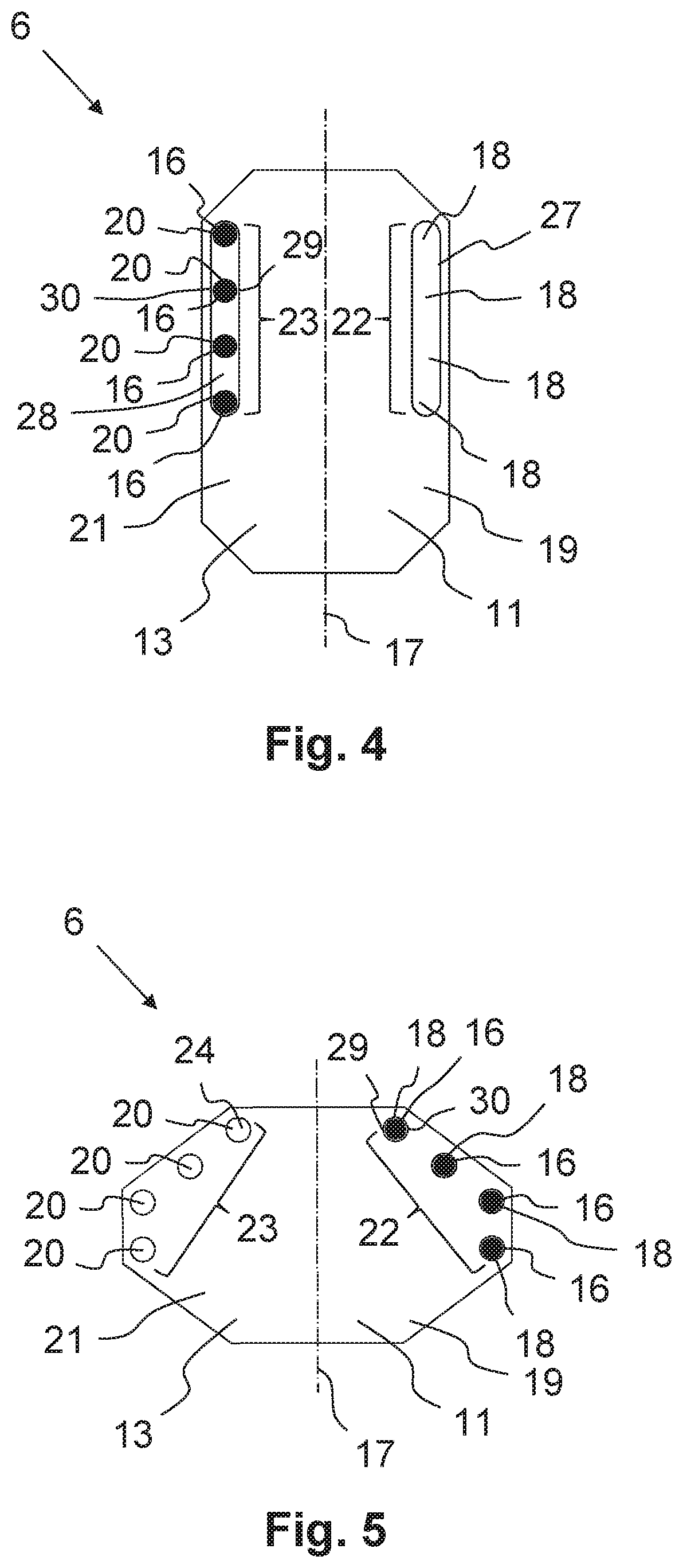
A scanning mirror for a laser scanning system includes a central axis, a mirror body, and a mirror surface on a front face of the mirror body. A first recess group is provided and includes a plurality of first recesses formed in the mirror body and arranged on a side of and spaced from the central axis as viewed from a back of the scanning mirror. A balancing mass is accommodated by the first recess group and includes at least one balancing body seated in at least one of the first recesses for balancing the scanning mirror. Each of the first recesses includes at least one radial stop against which the balancing body rests such that the balancing body is held in the first recess at a constant distance from the central axis. A method is also provided for balancing the scanning mirror.

Description

FIELD OF THE INVENTION[0001]The present invention relates to a scanning mirror for a laser scanning system, in particular a laser processing scanner and / or a sensor scanner of a laser processing device, comprising a mirror body and a mirror surface arranged on a front face of the scanning mirror. At least one first recess is formed in the mirror body, which is arranged on one side of a central axis of the scanning mirror, as viewed on the back of the scanning mirror, and is spaced apart from the central axis. At least one balancing body is provided, which is accommodated in the first recess and forms at least one part of a balancing mass for balancing the scanning mirror. Moreover, the invention relates to a method for balancing a scanning mirror, in which an imbalance of the scanning mirror is measured and the scanning mirror is balanced with the aid of balancing bodies.BACKGROUND[0002]Scanning mirrors, which are moved in a highly dynamic manner, i.e., for example, are rotated in a...

Claims


Application Information

Patent Timeline
IPC IPC(8): G02B26/08G02B7/182G02B7/198G02B26/10
CPCG02B7/1821G02B7/198G02B26/105
Inventor STRACKHARN, MATHIASWINKLER, MANUEL
Owner SCANLAB GMBH
Learn More