Robotic system for wind turbine airfoil maintenance

a technology for airfoil maintenance and robots, which is applied in the manufacture of engines, mechanical equipment, machines/engines, etc., can solve the problems of time-consuming, difficult and sometimes dangerous airfoil maintenance for technicians, and achieve the effect of minimizing drag and maximizing li

Active Publication Date: 2022-07-12
SAHNI RANBIR +4
View PDF31 Cites 1 Cited by
  • Summary
  • Abstract
  • Description
  • Claims
  • Application Information

AI Technical Summary

Benefits of technology

[0009]In yet another embodiment, an attachment may comprise a robotic arm that performs a tape laying procedure or a paint / print procedure where vortex generator tape (VGT) or paintable / printable UV curable material are attached to the surface of the airfoil at a airfoil location selected to maximize lift and minimize drag. A variation of this tool attaches individual vortex generators correctly spaced and positioned on the surface of the airfoil.
[0010]In another embodiment, a mechanical arm or other mechanism is used for in-situ filling of cracks or any other types of damages. Moreover, at least one visual device (optical or thermal camera) is mounted on the rover, to inspect the airfoil's surface for any surface damages. Using AI technology, the rover may detect different types of damages, and assist the computer or service tech to make decisions and perform remedial actions.

Problems solved by technology

However, such servicing of the airfoils can be challenging, time consuming and occasionally dangerous to those technicians that must work on and inspect the devices.

Method used


Image

  • Robotic system for wind turbine airfoil maintenance
  • Robotic system for wind turbine airfoil maintenance
  • Robotic system for wind turbine airfoil maintenance

Examples


Embodiment Construction

[0028]Although various embodiments are described herein, it is to be understood that different embodiments can share common features / tools / structures even if the embodiments are not specifically shown in that manner. In other words, one embodiment may show a tape applicator whereas another embodiment may show a paint sprayer, and it is to be understood that other embodiments may include both tools or some other combination, and each combination is properly deemed to be within the scope of the present invention.

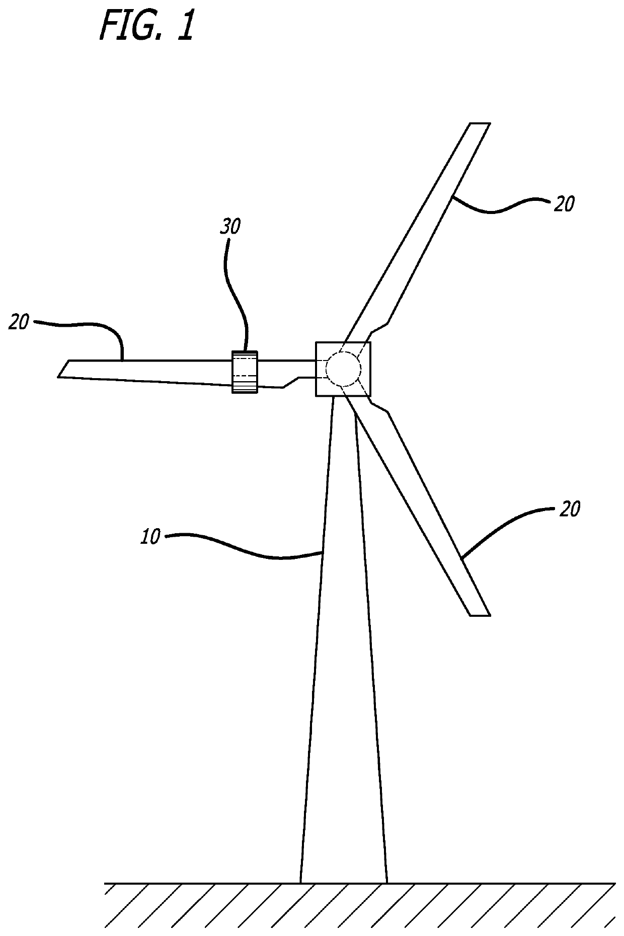
[0029]FIG. 1 illustrates an embodiment of present invention 30 situated on a horizontal axis wind turbine (“HAWT”) 10 that is found in many energy farms around the country. Horizontal axis wind turbines 10 use multiple airfoils 20 that are aerodynamically shaped like airplane wings that are rotated by the wind to generate electricity. The number of airfoils used for electric power generation typically varies depending upon the conditions, where the number of airfoils involves ...


PUM

PropertyMeasurementUnit
oblique anglesaaaaaaaaaa
rotationaaaaaaaaaa

Abstract

An automated wind turbine servicing system that includes a rover, and uses an active electro-mechanical gripping roller system to attach to a horizontally positioned airfoil and navigate along it in order to clean, inspect, service, or otherwise maintain the wind turbine airfoil. An electromechanical compression system adapts to various turbine airfoil profiles. Once secured to the airfoil, the rover activates a drive system that propels the rover along the airfoil as it travels along an upper edge, using wind pressure, the rover wheels' frictional adherence to the airfoil, and gravity to assist in coupling the rover to the airfoil. The rover, which preferably includes a robotic arm, is able to utilize multiple tools to perform various tasks such as inspecting, cleaning, sanding, repairing, painting and laying leading edge protection tape as well as vortex generators on the surface of the airfoil.

Description

CROSS-REFERENCES TO RELATED APPLICATIONS[0001]This application claims priority from U.S. Provisional Patent Application No. 62 / 847,510, filed May 14, 2019, the content of which is fully incorporated herein by reference.BACKGROUND[0002]It is known that the efficiency of wind turbines can be improved by cleaning, repairing, and improving the surface characteristics of the airfoils of the turbine, sometimes referred to as the blades. However, such servicing of the airfoils can be challenging, time consuming and occasionally dangerous to those technicians that must work on and inspect the devices. To service an airfoil, the turbine is stopped and the airfoil to be serviced is positioned at a 6 o'clock position, i.e. vertically downward. A worker is brought to the airfoil and uses various techniques to inspect, clean, repair and apply films or tape to the airfoil. Workers sometimes operate from a crane basket, or are suspended in a carrier by cables, or lowered from cables or ropes to th...

Claims


Application Information

Patent Timeline
Patent Type & Authority Patents(United States)
IPC IPC(8): F03D80/50B23P6/00F03D80/55
CPCF03D80/50B23P6/002F03D80/55F05B2230/80F05B2230/90B29C73/02B29C73/26B29C2073/262B29C2035/0827B08B1/04B08B1/008
Inventor SAHNI, RANBIRYOOZBASHIZADEH, MAHDIWAHLSTROM, AARONMONTGOMERY, TRAVAUGHNKHOSHNEVIS, BEROK
Owner SAHNI RANBIR
Why Eureka
Try Eureka