Lift enhancement assembly for aircraft with fixed wings

A technology of lifting components and aircraft, applied in the field of aircraft, can solve problems such as cumbersome and idle rotors, and achieve the effects of reducing resistance, increasing range, and increasing endurance

Pending Publication Date: 2022-05-27
UBIFLY TECH PTE LTD
View PDF1 Cites 0 Cited by
  • Summary
  • Abstract
  • Description
  • Claims
  • Application Information

AI Technical Summary

Problems solved by technology

However, during forward flight these rotors are idle and become a liability as they provide no lift

Method used


Image

  • Lift enhancement assembly for aircraft with fixed wings
  • Lift enhancement assembly for aircraft with fixed wings
  • Lift enhancement assembly for aircraft with fixed wings

Examples


Embodiment Construction

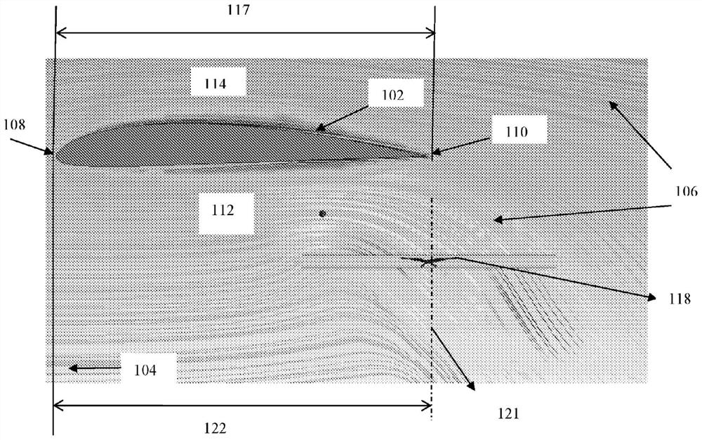
[0037] In aircraft with fixed wings, lift is generated by the wings during forward flight. As air flows over the wing during forward flight, the shape and direction of the wing creates a pressure field, with the low pressure at the top of the wing called the suction side and the high pressure below the wing called the pressure side. Lift is created by the pressure field.

[0038] Additionally, the vertical rotors are set up for use during takeoff, landing and hovering. But during forward flight, the vertical rotor becomes a burden. The present invention develops a lift assembly that utilizes the lift provided by operating the vertical rotor during forward flight. The presence of the rotor and its operation changes the flow field and thus the pressure field around the wing.

[0039] figure 1 The airflow in front of the fixed wing and the operable vertical rotor in an embodiment of the invention is shown. A section of the fixed wing 102 is shown. Arrow 104 indicates the di...


PUM


Abstract

The invention relates to a lift assembly (300) in an aircraft. The lift assembly (300) includes a wing (102) and at least one vertical rotor (118) disposed below the wing (102). The vertical axis (121) of the vertical rotor (118) is located within the span of the wing (102). The vertical rotor (118) is operable during forward flight of the aircraft. A placement distance (122) between the leading edge (108) and the vertical axis (121) of the vertical rotor (118) is a factor of the RPM of the rotor (118), the angle of attack (116) of the wing, and the chord (117). The lift assembly (300) produces a higher lift than the sum of lift produced individually by the wings (102) and the rotors (118), so that small wings can be provided and thus reduced drag can be produced.

Description

technical field [0001] The present invention relates to an aircraft. In particular, the present invention relates to lift assemblies in aircraft. Background technique [0002] The power of the aircraft is controlled by counteracting the drag and gravity acting on the aircraft. Lift is used to overcome the effects of gravity on the power of the aircraft. Lift is provided by fixed wings, which are designed to create a pressure differential during forward flight to generate lift. Alternatively, as in the case of a rotorcraft, the rotors may generate lift. A set of rotors can be used to generate lift during vertical takeoff, landing, or hovering in the air. However, during forward flight, these rotors are idle and become cumbersome as they do not provide lift. [0003] CN103043212A discloses a composite aircraft composed of fixed wings and electric multi-rotors, including a set of electric multi-rotor power systems and a general controller. The fixed-wing power system and ...

Claims


Application Information

Patent Timeline
Patent Type & Authority Applications(China)
IPC IPC(8): B64C27/26
CPCB64C27/26B64C3/42B64C9/24B64C9/38B64C29/0016
Inventor 查克拉瓦提·思偌奥姆卡尔·纳伦德拉·沃尔维卡尔高德姆·R斯里·拉加夫·R蓝普拉卡希·拉维钱德兰
Owner UBIFLY TECH PTE LTD
Why Eureka
Try Eureka