Windscreen wiper arm, particularly for automobiles

a technology for windscreen wipers and automobiles, which is applied in vehicle maintenance, vehicle cleaning, transportation and packaging, etc., can solve the problems of large amount of liquid (consumption), the windscreen cannot be effectively cleaned, and the relative large amount of washing fluid cannot effectively reach the wiping pattern on the windscreen to be wiped, etc., to achieve the effect of effectively cleaning the windscreen

Active Publication Date: 2022-06-14
TRICO BELGIUM SA
View PDF6 Cites 0 Cited by
  • Summary
  • Abstract
  • Description
  • Claims
  • Application Information

AI Technical Summary

Benefits of technology

[0003]It is an object of the invention to obviate these disadvantages, in the sense that at minimum costs—without using complex machinery and additional tools—a simple windscreen wiper arm is proposed to effectively clean a windscreen to be wiped, without damaging parts of a car, where less washing liquid is required to clean the windscreen to be wiped.
[0008]According to the invention, a windshield wiper arm is provided with a nozzle for spraying a washing liquid onto the windscreen to be wiped. The nozzle is detachably connected to the adapter through a key hole connection. A keyhole connection enables a rapid and reliable joining of the nozzle and the adapter. By connecting the nozzle directly to the adapter of the windscreen wiper arm, the nozzle is not only fixed to the windscreen wiper arm in a reliable and controllable manner, although detachably in case of repair or replacement of the nozzle, but the nozzle is located at a very small distance relative to the windscreen to be wiped and is allowed to directly follow any oscillatory movement of the windscreen wiper arm, so that the washing fluid exiting the nozzle can be effectively sprayed thereon, with all positive consequences involved as to effective cleaning of the windscreen to be wiped and safe visibility for a driver. Further, the nozzle may be used as a first nozzle in combination with a second nozzle located on the windscreen wiper arm for spraying a washing liquid onto the windscreen to be wiped. In that case the washing liquid is sprayed from at least two locations (on the adapter and on the windscreen wiper arm) onto the windscreen to be wiped, namely washing liquid exiting from the first nozzle connected to the adapter, as well as washing liquid exiting from the second nozzle connected to the windscreen wiper arm. Thus, the windscreen can be cleaned efficiently over a very large wiping area thereof, particularly at high speeds. In that case, the first and second nozzles are preferably connected to only one inlet for the washing fluid, so that the first and second nozzles are in liquid contact with each other.
[0012]To enhance its elasticity in order to snap through the reduced hole, the protrusion preferably has an inner hole, preferably a concentric inner hole inside the shank.

Problems solved by technology

A disadvantage of the windscreen wiper arm known from the above German patent publication is that the windscreen wiper arm is often used in combination with a nozzle fixedly mounted on (or below) a bonnet of a car for spraying a washing liquid onto the car's windscreen to be wiped.
In practice it has become apparent that the windscreen cannot effectively be cleaned by a combination of the known windscreen wiper arm and the nozzle, as the nozzle emits the washing fluid at a large distance relative to the windscreen, so that a relatively large amount of the washing fluid does not effectively reach a wiping pattern on the windscreen to be wiped.
Further, it has become apparent that in the prior art, a large amount of liquid (consumption) is required in an attempt to clean the windscreen to be wiped.
Further, if the washing fluid is spread onto the car's body instead of onto the windscreen to be wiped, it may damage the car.
Indeed, ethanol, methanol and other components of the washing fluid are believed to have a corrosive effect on paint, rubber, car wax and plastics, for example.

Method used


Image

  • Windscreen wiper arm, particularly for automobiles
  • Windscreen wiper arm, particularly for automobiles
  • Windscreen wiper arm, particularly for automobiles

Examples


Embodiment Construction

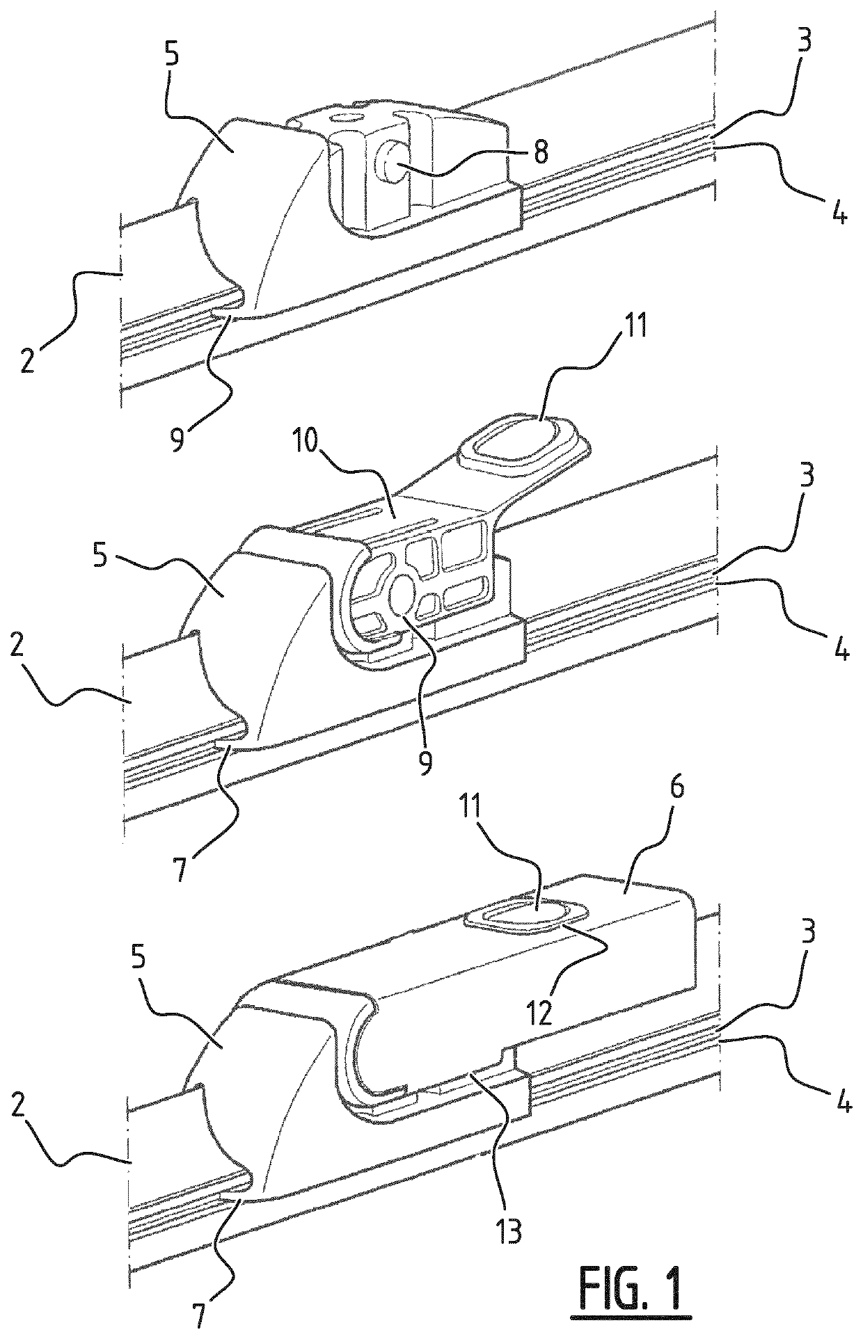
[0022]FIG. 1 shows a windscreen wiper device 1 of the flat blade type including a wiper blade 2 having opposing longitudinal grooves 3 formed in the longitudinal sides of the wiper blade 2. Longitudinal strips 4 (“flexors”) made of spring band steel are fitted in the longitudinal grooves 3. The strips 4 form a flexible carrier element for the rubber wiper blade 2, which is thus biased in a curved position (the curvature in operative position being that of a windscreen to be wiped). The windscreen wiper device 1 also includes a connecting device 5 of plastic material for a windscreen wiper arm 6. The connecting device 5 comprises clamping members 7 that are integral therewith, which engage longitudinal sides of the strips 4 that face away from each other. Thus, the connecting device is firmly attached to the unit consisting of the wiper blade 2 and the strips 4. The windscreen wiper arm 6 is pivotally connected to the connecting device 5 about a pivot axis near one end thereof, and i...


PUM


Abstract

A windscreen wiper arm, particularly for automobiles, that is able to oscillate upwardly and downwardly between a downward position and an upward position. One end of the windscreen wiper arm is adapted to be pivotally connected to a mounting head mounted on a drive shaft. Another end of the windscreen wiper arm is rigidly connected to an adapter adapted to be connected to an elongated wiper blade to be placed in abutment with a windscreen to be wiped. The adapter, at the location of its connection to the wiper blade, has a U-shaped cross-section with a base and two spaced-apart legs. The U-shaped cross-section is preferably mounted offset in a plane of the base relative to a longitudinal axis of the windscreen wiper arm. The windscreen wiper arm is provided with a nozzle for spraying a washing liquid onto the windscreen to be wiped. The nozzle is detachably connected to the adapter through a key hole connection.

Description

BACKGROUND OF THE INVENTION[0001]German patent publication no. 34 33 106 (SWF Auto-Electric GmbH) discloses an oscillating windscreen wiper arm comprising an arm member pivotally connected to a mounting head by means of a pivot pin. The arm member has a substantially U-shaped cross-section near the pivot pin having two side walls. A part of the mounting head extends between the side walls and beyond the pivot pin. A spring is hooked with its first end on a pin on the mounting head. The arm member is connected to a wiper rod, where one end of the wiper rod extends inside the U-shaped cross-section of the arm member. The side walls of the arm member are locally folded around the wiper rod, while a holder is folded around the end of the wiper rod. The spring of this prior art windscreen wiper arm is hooked with its first end on the pin on the mounting head and with its second end on two eyes of the holder.[0002]A disadvantage of the windscreen wiper arm known from the above German pate...

Claims


Application Information

Patent Timeline
Patent Type & Authority Patents(United States)
IPC IPC(8): B60S1/52B60S1/40
CPCB60S1/522B60S1/4045
Inventor BOLAND, XAVIER
Owner TRICO BELGIUM SA
Why Eureka
Try Eureka