Pneumatic tire

a technology of pneumatic tires and compression lugs, which is applied in the field of pneumatic tires, can solve the problems of high-speed durability deterioration, tire noise, and deformation of elastic fixed bands, and achieve the effects of reducing stress, reducing vibration, and suppressing damage to band-like sound absorption members

Active Publication Date: 2022-05-17
THE YOKOHAMA RUBBER CO LTD
View PDF23 Cites 0 Cited by
  • Summary
  • Abstract
  • Description
  • Claims
  • Application Information

AI Technical Summary

Benefits of technology

[0005]The present technology provides a pneumatic tire that can promote heat dissipation from a band-like sound absorbing member, and improve high-speed durability, as well as reliving stress occurring on the band-like sound absorbing member during a rolling motion, and improving the durability of the band-like sound absorbing member, by providing a cut on the band-like sound absorbing member adhered to an inner surface of the tire.

Problems solved by technology

Cavernous resonance caused by the vibration of the air filled in a cavity portion of a tire is one cause of tire noise.
However, in a case where securing the sound absorbing member is dependent on the elastic fixed band, problems occur where the elastic fixed band deforms during high speed travel.
However, in this case, the band-like sound absorbing member is directly applied to a tire inner surface, and therefore, problems occur where heat accumulation is generated on a tread portion, and high-speed durability deteriorates due to heat accumulation.
Furthermore, in a case where the band-like sound absorbing member is directly applied on a tire inner surface, problems occur where the band-like sound absorbing member cannot follow tire deflection and therefore is damaged.
However, in a case where cuts extending in two mutually intersecting directions are provided on the band-like sound absorbing member, a force with regard to a tire circumferential direction acts on blocks demarcated by the cuts during a rolling motion, and thus collapsing of the blocks occurs.
The collapsing of the blocks repeatedly occurs during a rolling motion, and therefore, the blocks rub against each other, which is a factor leading to damaging of the band-like sound absorbing member.
In particular, in a case where only inclined cuts are provided without providing cuts extending in a tire lateral direction or tire circumferential direction, the blocks are subjected to stress with regard to the tire circumferential direction based on collapsing of two blocks positioned forward in a rotational direction, and therefore, collapsing of the blocks subjected to the stress increases, and thus the band-like sound absorbing member is prone to further damage.

Method used


Image

  • Pneumatic tire
  • Pneumatic tire
  • Pneumatic tire

Examples


examples

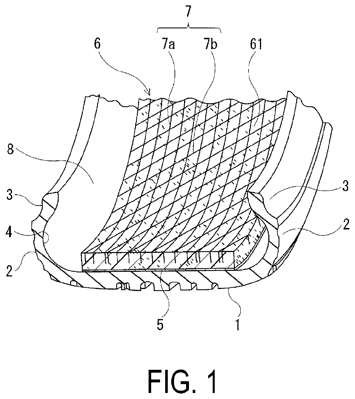
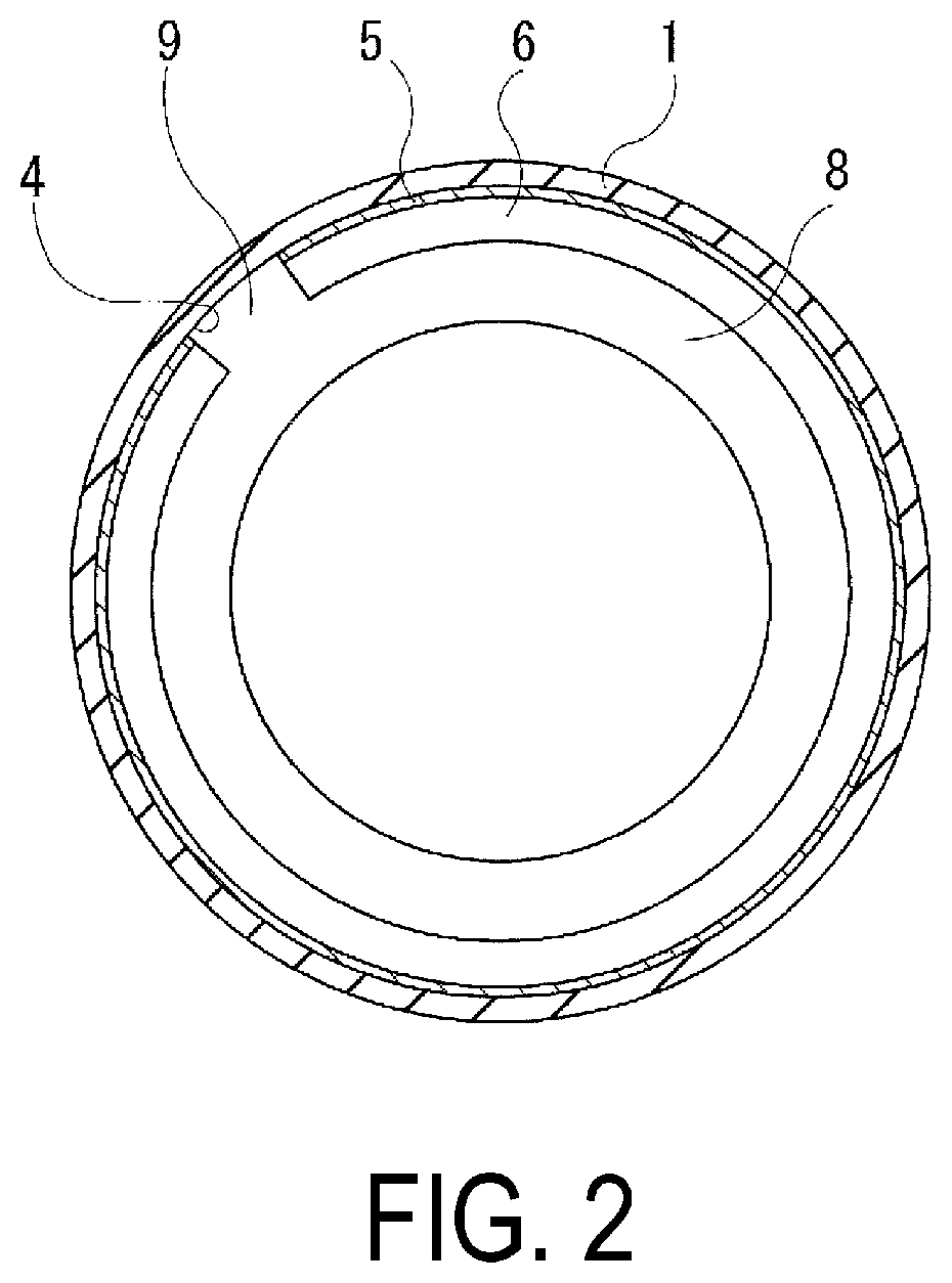
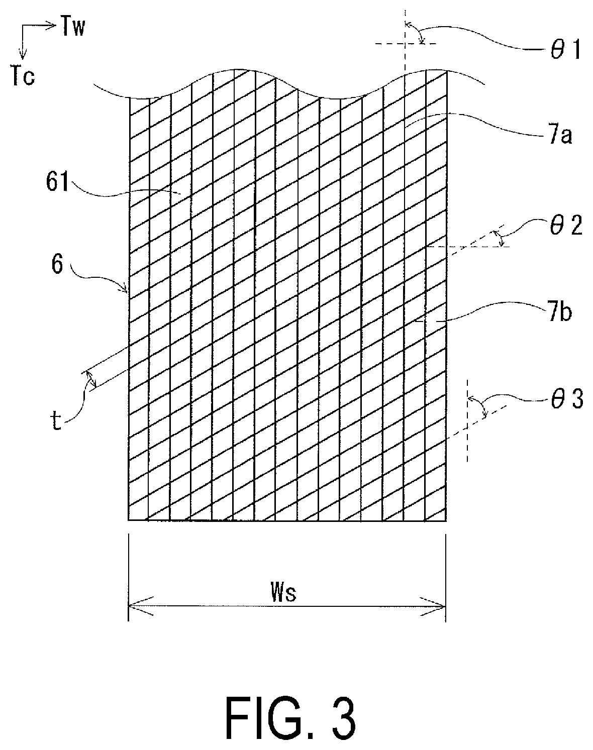
[0033]Tires of Examples 1 to 20 having a plurality of cuts extending in two mutually intersecting directions on a band-like sound absorbing member were prepared for a pneumatic tire provided with an annular-shaped tread portion extending in a tire circumferential direction, a pair of sidewall portions disposed on both sides of the tread portion, and a pair of bead portions disposed on an inner side in a tire radial direction of the sidewall portions, at a tire size of 275 / 35ZR20, where a band-like sound absorbing member is adhered on an inner surface of the tread portion in the tire circumferential direction, and the band-like sound absorbing member has a plurality of cuts extending in two mutually intersecting directions.

[0034]In Examples 1 to 20, the presence / absence of a cut, angle θ1 with regard to the tire lateral direction of the first cut, angle θ2 with regard to the tire later direction of the second cut, interval of the cuts (interval t / width Ws×100%), and depth of the cuts...


PUM


Abstract

A pneumatic tire is provided, including: an annular-shaped tread portion extending in a tire circumferential direction; a pair of sidewall portions disposed on both sides of the tread portion; and a pair of bead portions disposed on an inner side in a tire radial direction of the sidewall portions; wherein a band-like sound absorbing member is adhered on an inner surface of the tread portion in the tire circumferential direction; and the band-like sound absorbing member has a plurality of cuts extending in two mutually intersecting directions, and of the cuts, a cut extending in one direction is a cut extending parallel with regard to a tire lateral direction or tire circumferential direction.

Description

TECHNICAL FIELD[0001]The present technology relates to a pneumatic tire, and particularly relates to a pneumatic tire that can promote heat dissipation from a band-like sound absorbing member, and improve high-speed durability, as well as relieving stress occurring on the band-like sound absorbing member during a rolling motion, and improving the durability of the band-like sound absorbing member, by providing a cut on the band-like sound absorbing member adhered to an inner surface of the tire.BACKGROUND ART[0002]Cavernous resonance caused by the vibration of the air filled in a cavity portion of a tire is one cause of tire noise. Cavernous resonance is caused by a tread portion of a tire contacting a road surface during vehicle travel vibrating due to unevenness on the road surface, and the vibration is caused by air inside a cavity portion of a tire vibrating. The cavernous resonance has a frequency range where noise is generated, and reducing the noise level of the frequency ran...

Claims


Application Information

Patent Timeline
Patent Type & Authority Patents(United States)
IPC IPC(8): B60C19/00B60C5/00
CPCB60C19/002B60C5/00
Inventor NARUSE, MASAHIROSHINZAWA, TATSUROHOSHIBA, TAKASHI
Owner THE YOKOHAMA RUBBER CO LTD
Why Eureka
Try Eureka