
Doppler measurement system and method

a measurement system and doppler technology, applied in the field of ultrasonic doppler measurement systems, can solve the problems of reducing the (slow-time) nyquist frequency, aliasing of already attenuated fast objects, and reducing the slow-time sampling rate and hence the unaliased doppler frequency limi

Active Publication Date: 2022-04-12
MANSOUR OMAR +1
View PDF14 Cites 0 Cited by
  • Summary
  • Abstract
  • Description
  • Claims
  • Application Information

AI Technical Summary

Benefits of technology

The patent describes a system for measuring flow using ultrasonic waves. The system includes a random generator that selects a random number to control the emission of ultrasonic pulses. The pulses are emitted at a target and reflected back to the system. The system has an ultrasonic array transducer that can adjust the steering angle of the pulses to create a random sweep. The system also has a memory to store the echo data and a processor to extract a Doppler parameter from the data. The system can display the Doppler parameter on a screen. The technical effect of this system is that it allows for more accurate and precise measurement of flow in a non-invasive way.

Problems solved by technology

An additional drawback of compounding is that the HRI frame rate is reduced to PRF / N, thereby reducing the (slow-time) Nyquist frequency, so aliasing can occur for the already attenuated fast objects.
Increasing N reduces the angle increment, thereby improving the beam profile, but it reduces the slow-time sampling rate and hence the unaliased Doppler frequency limit.

Method used


Image

  • Doppler measurement system and method
  • Doppler measurement system and method
  • Doppler measurement system and method

Examples


Embodiment Construction

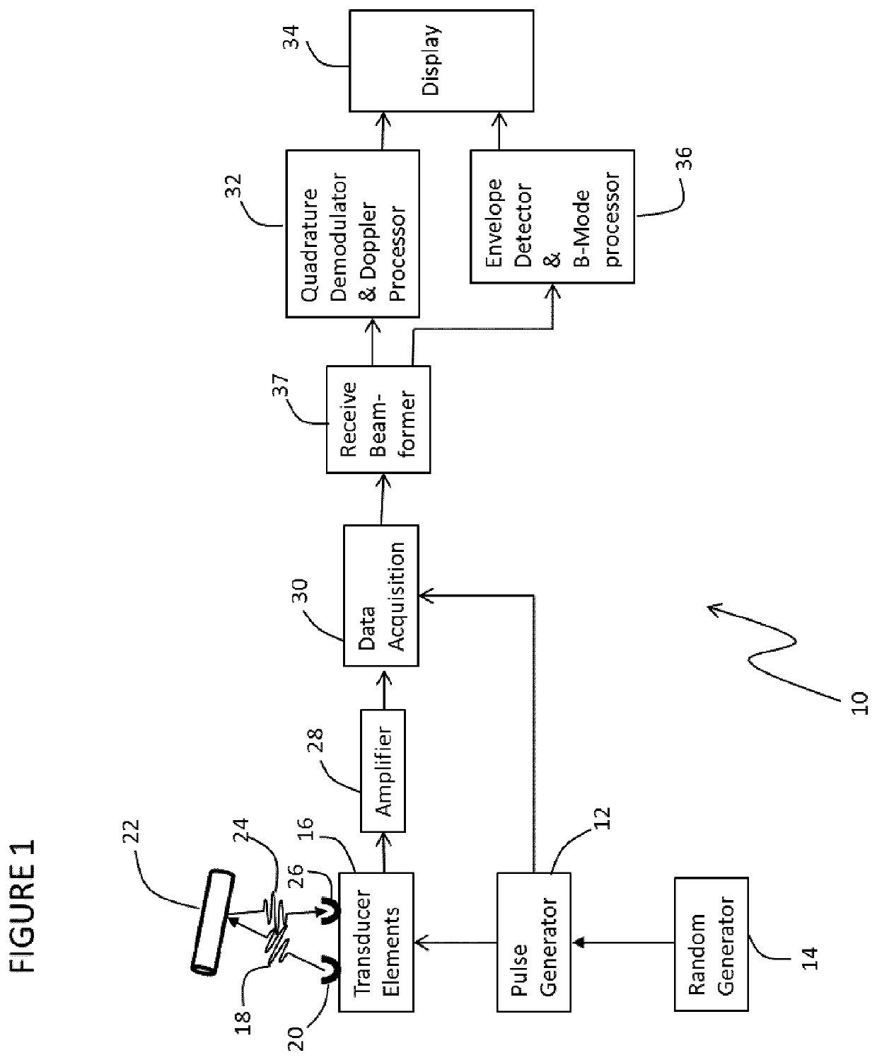
[0040]Referring to the drawings, a Doppler flow measurement system and method is now described.

[0041]FIG. 1 shows a block diagram schematic view of a Doppler flow measurement system 10. The Doppler flow measurement system employs the Doppler effect to determine parameters to characterize flow of a fluid or motion or deformation of a tissue. The system 10 comprises a pulse generator source 12 for outputting pulsed electrical signals that are communicated to transducer 16. Transducer 16 includes multiple elements and is configured to convert pulsed electrical signals into ultrasonic pulses. Transducer 16 emits an ultrasonic transmit pulse 18 from a transmitter element 20 towards a target sample 22. The transducer 16 is also configured to receive and capture a backscattered echo 24 from the target sample 22 at a receiver element 26. The multiple elements of the transducer 16 are each configured to both transmit and receive. In a typical transmit / receive cycle, the ultrasonic transmit p...


PUM


Abstract

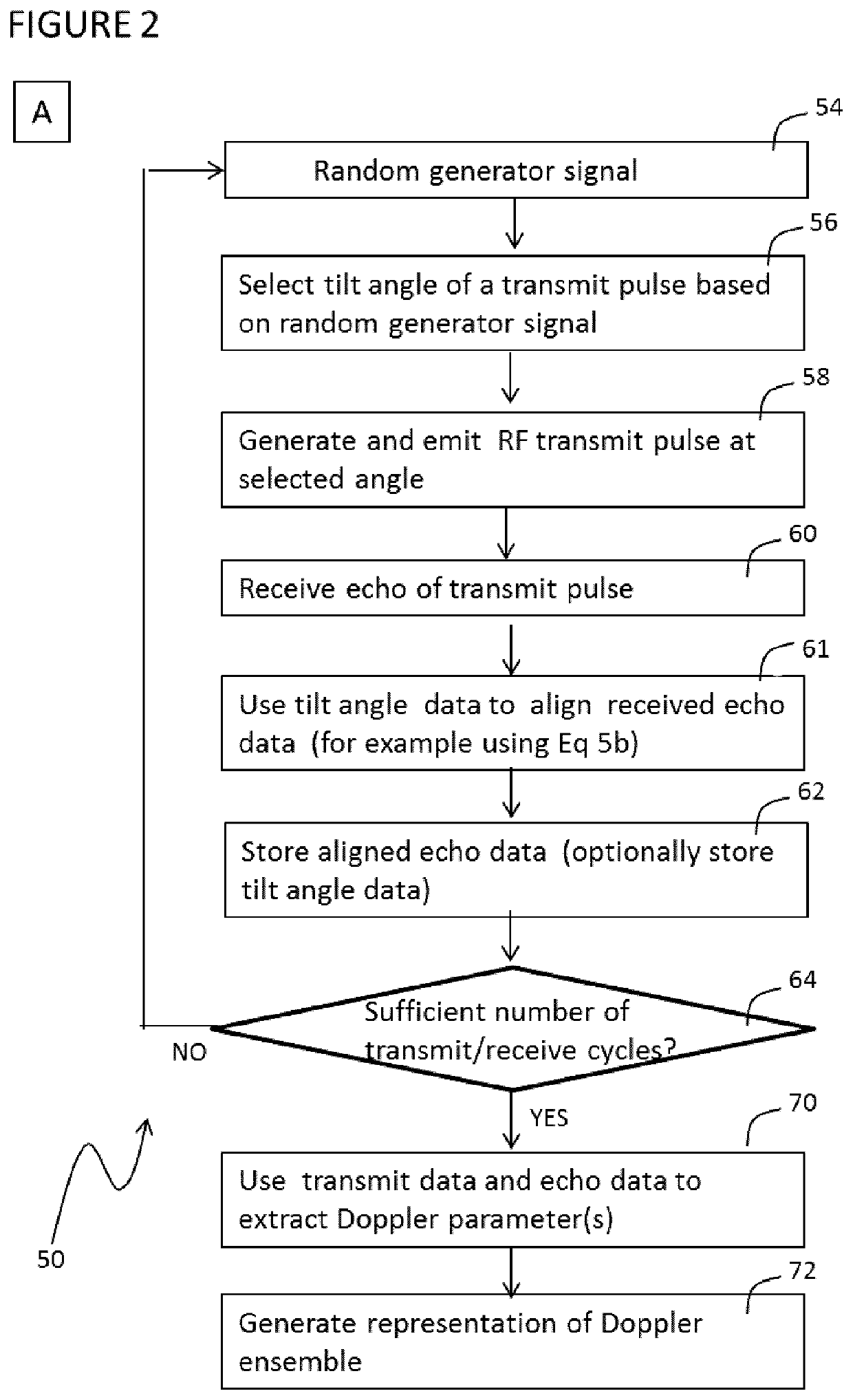
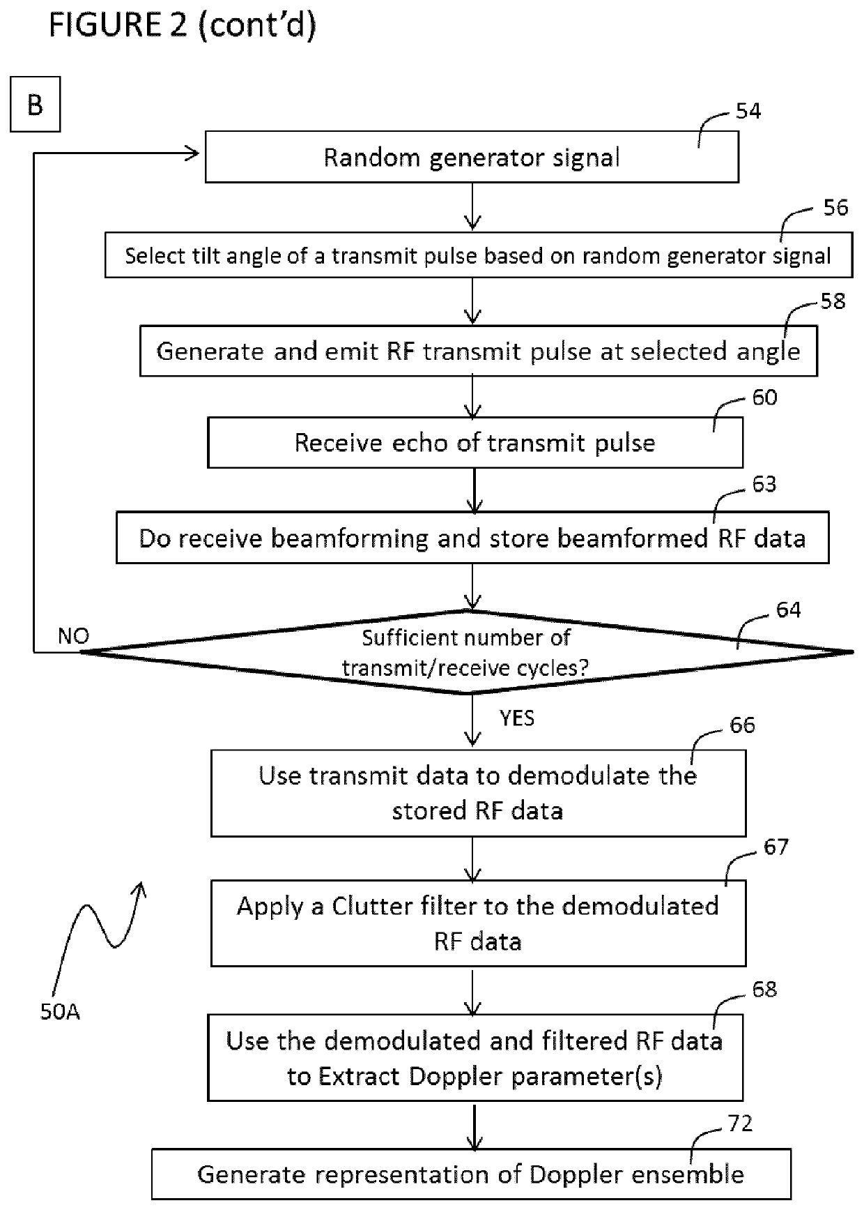
A Doppler measurement system includes a random generator outputting a control signal encoding a random selection, and an ultrasonic array transducer for emitting a sequence of transmit pulses at a target at either an adjustable steering angle (plane wave imaging) or from a selectable non-sequential transducer element order (synthetic aperture imaging) corresponding to the random selection and for receiving an echo of each transmit pulse reflected from the target. Each transmit pulse is independently adjusted to a steering angle (plane wave imaging) or selectable transducer element order (synthetic aperture imaging) corresponding to a unique random selection so that the sequence of transmit pulses is a random sweep. The system can also include a memory for storing echo data, and a processor connected to the memory for using transmit data and echo data to extract a Doppler parameter. Methods of Doppler measurement and computer-readable medium can incorporating the measurement system.

Description

CROSS REFERENCE TO RELATED APPLICATIONS[0001]This application is the U.S. National Phase of International Application No. PCT / CA2017 / 050247, filed Feb. 24, 2017, designating the U.S. and published in English as WO 2017 / 143456 A1 on Aug. 31, 2017 which claims the benefit of U.S. Provisional Patent Application No. 62 / 300,600 filed Feb. 26, 2016. Any and all applications for which a foreign or domestic priority claim is identified here or in the Application Data Sheet as filed with the present application are hereby incorporated by reference under 37 CFR 1.57.BACKGROUND OF THE INVENTIONField of the Invention[0002]The present invention relates to ultrasound measurement technology, and more particularly to ultrasonic Doppler measurement systems.Description of the Related Art[0003]Pulsed Doppler ultrasound systems can be used to measure motion, such as a flow of a liquid. For example, medical applications include measuring blood flow or tissue motion where ultrasonic pulses are directed i...

Claims


Application Information

Patent Timeline
Patent Type & Authority Patents(United States)
IPC IPC(8): A61B8/08A61B8/06G01S15/50G01F1/66G01S15/89A61B8/00G01S7/52G01F1/663
CPCA61B8/488A61B8/06A61B8/4488A61B8/4494A61B8/463G01F1/66G01F1/663G01S7/52095G01S15/50G01S15/8927G01S15/8977G01S15/8979G01S15/8981G01S15/8984G01S15/8988A61B8/5246
Inventor MANSOUR, OMARLACEFIELD, JAMES
Owner MANSOUR OMAR
Learn More