
Transmission and method for producing such a transmission

a transmission and transmission technology, applied in the field of transmission, can solve the problems of relatively large increase in the dead weight of the housing, high cost of the housing with such cooling fins, etc., and achieve the effects of reducing the dead weight, improving the cooling capacity, and increasing the surface area

Active Publication Date: 2022-04-05
FLENDER GMBH
View PDF16 Cites 0 Cited by
  • Summary
  • Abstract
  • Description
  • Claims
  • Application Information

AI Technical Summary

Benefits of technology

[0009]A significant advantage of providing cooling elements made from open-cell metal foam over conventional cooling fins resides in a significantly larger surface area and improved cooling capacity associated therewith. Moreover, such cooling elements made from open-cell metal foam have a lower dead weight than cooling fins, so that the housing of a transmission according to the invention can be made lighter than a housing with cooling fins while still maintaining a comparable cooling capacity. Another advantage associated with the use of separate cooling elements made from open-cell metal foam is that the cooling elements can be secured later on to suit a demand at hand, for example a housing manufactured by casting. This allows simple and flexible adjustment of the cooling capacity to the demand at hand. In particular, such retrofitting of cooling elements makes it possible to achieve a wide range of cooling capacities on the basis of a standard housing, and this allows low-cost series manufacture when housings of essentially same design with different cooling capacity are required.
[0010]According to another advantageous feature of the present invention, the cooling element can be made of aluminum or copper. Using aluminum and copper has the benefits of good thermal conductivity, while at the same time being of low weight.
[0011]According to another advantageous feature of the present invention, the cooling element can have a plate-shaped configuration. This allows simple and flexible handling. For example, the shape of the underside can be matched to the shape of a region of the outer surface of the housing. Thus, the cooling element can have an underside in the form of a circular ring segment to enable its simple securement on a housing, the outer surface of which is likewise in the form of a circular ring segment, at least in one region thereof.
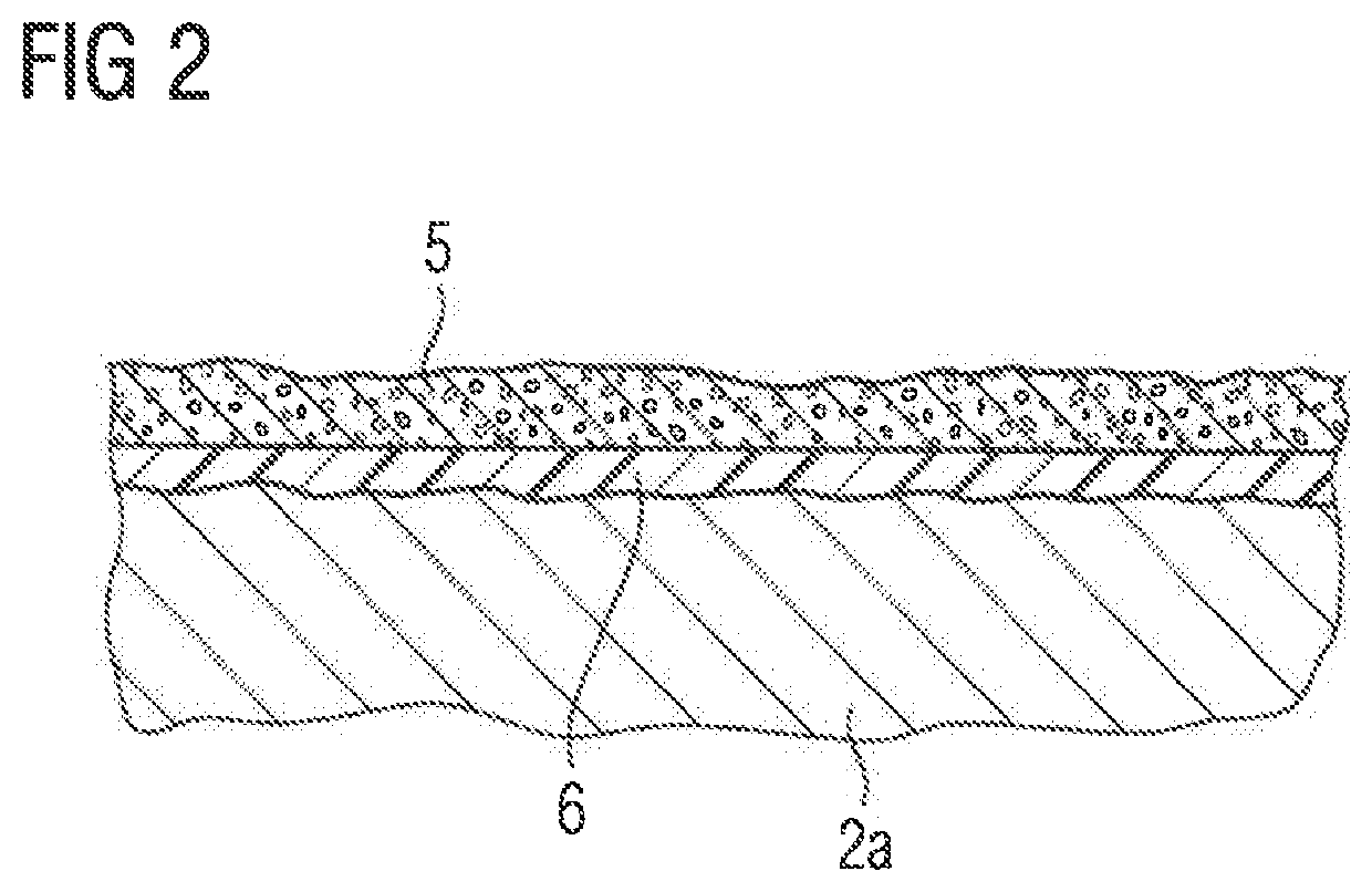
[0012]According to another advantageous feature of the present invention, an intermediate layer containing silicone and thermally conductive particles can be provided between the cooling element and the housing. This is advantageous especially when the surface of the housing on which the cooling element is to be arranged is uneven, as is often the case when the housing is produced by casting, for example.
[0013]According to another advantageous feature of the present invention, the cooling element can be secured on the housing by a screw connection and / or adhesive bonding. This allows very simple mounting of the cooling element on the housing. As an alternative or in addition, the cooling element can be secured on the housing by a magnet.
[0015]According to another advantageous feature of the present invention, an intermediate layer containing silicone and thermally conductive particles can be provided between the cooling element and the housing. As a result, irregularities in the housing surface in particular can be compensated.

Problems solved by technology

However, housings with such cooling fins become very expensive when compared with housings without cooling fins.
Moreover, the formation of cooling fins is associated with a relatively large increase in the dead weight of the housing, which is undesirable in many cases.

Method used


Image

  • Transmission and method for producing such a transmission
  • Transmission and method for producing such a transmission

Examples


Embodiment Construction

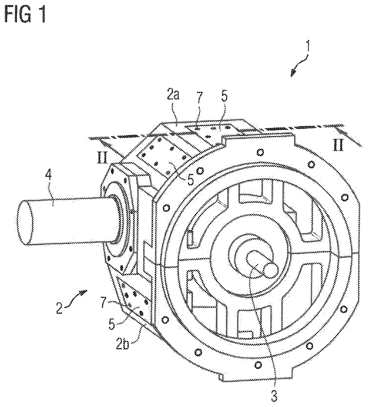
[0020]Throughout all the figures, same or corresponding elements may generally be indicated by same reference numerals. These depicted embodiments are to be understood as illustrative of the invention and not as limiting in any way. It should also be understood that the figures are not necessarily to scale and that the embodiments may be illustrated by graphic symbols, phantom lines, diagrammatic representations and fragmentary views. In certain instances, details which are not necessary for an understanding of the present invention or which render other details difficult to perceive may have been omitted.

[0021]Turning now to the drawing, and in particular to FIG. 1, there is shown a schematic perspective view of a transmission according to present invention, generally designated by reference numeral 1. In the non-limiting example shown here, the transmission 1 is embodied as a spur gear transmission configured as a bevel-and-spur gear train. However, it will be understood that the ...


PUM

PropertyMeasurementUnit
thermally conductiveaaaaaaaaaa
cooling capacityaaaaaaaaaa
transmissionaaaaaaaaaa

Abstract

A transmission includes a housing made from a metallic material and is provided with a cooling structure in the form of a cooling element made from open-cell metal foam. The cooling element can be secured on the housing, in particular on an outer surface of the housing, by a screw connection and / or adhesive bonding and / or magnetically.

Description

CROSS-REFERENCES TO RELATED APPLICATIONS[0001]This application claims the priority of European Patent Application, Serial No. 18195645.9, filed Sep. 20, 2018, pursuant to 35 U.S.C. 119(a)-(d), the disclosure of which is incorporated herein by reference in its entirety as if fully set forth herein.BACKGROUND OF THE INVENTION[0002]The present invention relates to a transmission and to a method for producing such a transmission.[0003]The following discussion of related art is provided to assist the reader in understanding the advantages of the invention, and is not to be construed as an admission that this related art is prior art to this invention.[0004]A crucial factor in the transmission engineering sector involves dissipation of heat, generated in the transmission, from the transmission housing so as to ensure proper operation of the transmission for an extended period. For this purpose, the transmission can be provided with an active cooling device. As an alternative or in additio...

Claims


Application Information

Patent Timeline
Patent Type & Authority Patents(United States)
IPC IPC(8): F16H57/04B32B7/12B32B15/04F16H57/032B32B15/20
CPCF16H57/0419B32B7/12B32B15/046B32B15/20F16H57/032B32B2266/06F16H57/0416F16H57/04F16H57/0412
Inventor PAPIES, JENNIFER
Owner FLENDER GMBH
Learn More