An inspection robot
A technology for inspection robots and walking mechanisms, applied in the field of inspection robots, can solve the problems of inconvenient robot inspection and transportation, complex inspection robot structure, affecting inspection efficiency, etc. Light, real-time effect
- Summary
- Abstract
- Description
- Claims
- Application Information
AI Technical Summary
Problems solved by technology
Method used
Image
Examples
Embodiment 1
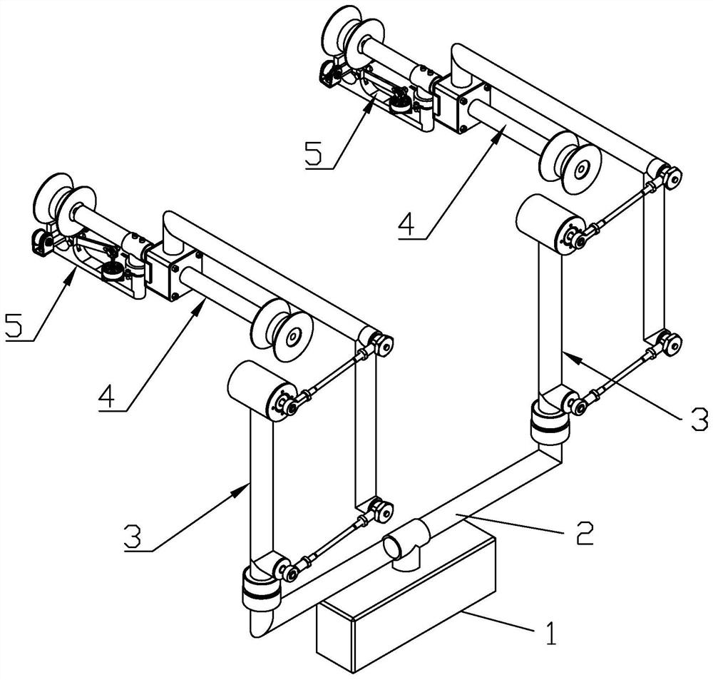
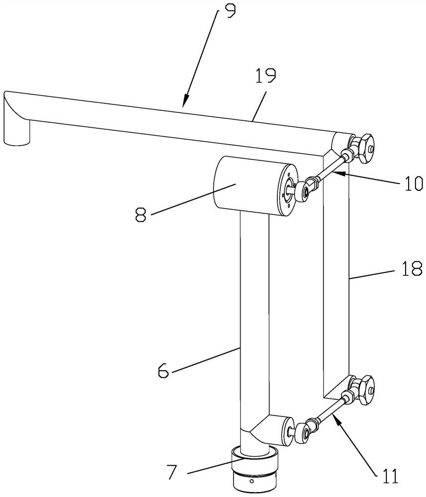
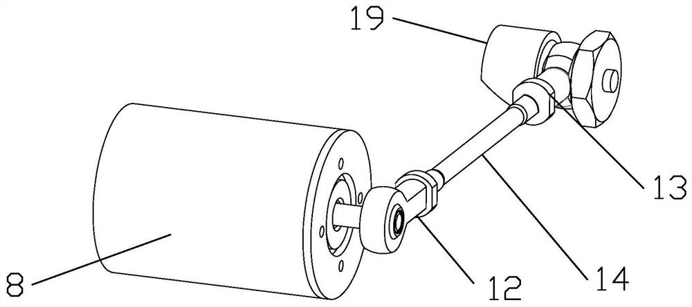
[0040] see figure 1 , a patrol robot, comprising a control box 1, a main bracket 2, a four-bar linkage mechanism 3, a traveling mechanism 4 and a safety mechanism 5, the lower side of the middle part of the main bracket 2 is provided with the control box 1, and the control box 1 There are various control units, motor drivers and other electrical components inside. The four-bar linkage mechanism 3 is provided on both ends of the main bracket 2, and the walking mechanism 4 is provided on the top side of the four-bar linkage mechanism 3. Said safety mechanism 5 is provided on said running mechanism 4 . Specifically, the four-bar linkage mechanism 3, the walking mechanism 4 and the safety mechanism 5 are all provided with two pairs, forming the forearm part and the rear arm part of the inspection robot. The forearm part is located at the front of the main support 2, and the rear arm part is located at The rear part of the main support 2, the forearm part and the rear arm part hav...
Embodiment 2
[0076] The difference between this embodiment and embodiment 1 is: for details, refer to Figure 12 and Figure 13 , The four-bar linkage mechanism 3 can be changed into an electric lifting rod mechanism driven by a screw motor and can also realize the same function, and other technical features are the same as in embodiment 1. Specifically, the electric lifting rod mechanism driven by a lead screw motor includes a bottom rotation adjustment motor 39, a vertical cylinder 40 and a lead screw motor (not shown in the figure), and the rotation adjustment motor 39 is located at the bottom of the screw motor drive. The bottom of the electric lifting rod mechanism is the same as the joint motor 7 in Embodiment 1. The top of the rotation adjustment motor 39 is provided with a vertical cylinder 40, and the vertical cylinder 40 is provided with a screw motor connected with a lifting rod. Bracket9.
PUM
 Abstract
Description
Claims
Application Information
 - R&D
- Intellectual Property
- Life Sciences
- Materials
- Tech Scout
- Unparalleled Data Quality
- Higher Quality Content
- 60% Fewer Hallucinations
Browse by: Latest US Patents, China's latest patents, Technical Efficacy Thesaurus, Application Domain, Technology Topic, Popular Technical Reports.
© 2025 PatSnap. All rights reserved.Legal|Privacy policy|Modern Slavery Act Transparency Statement|Sitemap|About US| Contact US: help@patsnap.com


