
Modular floor covering system

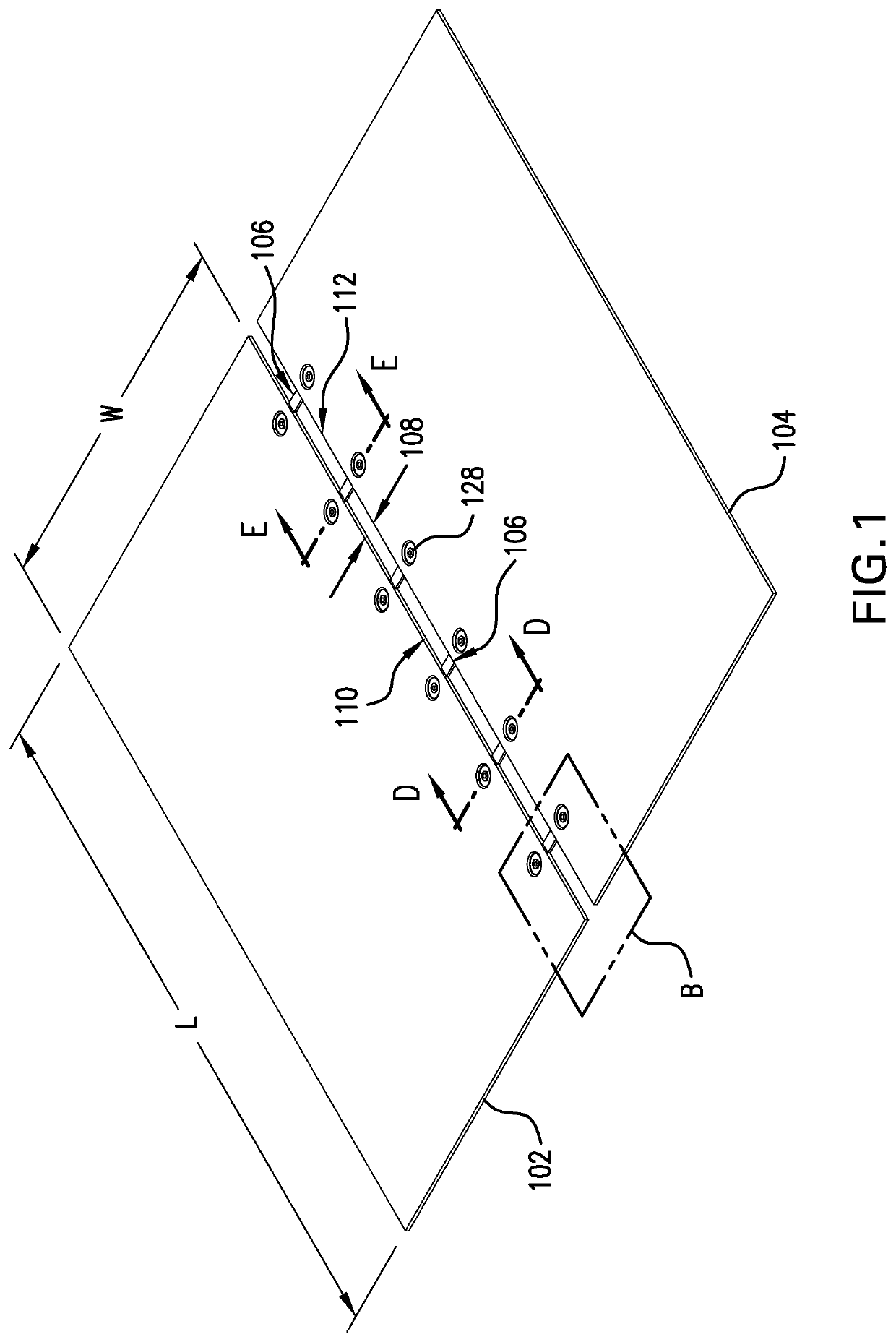
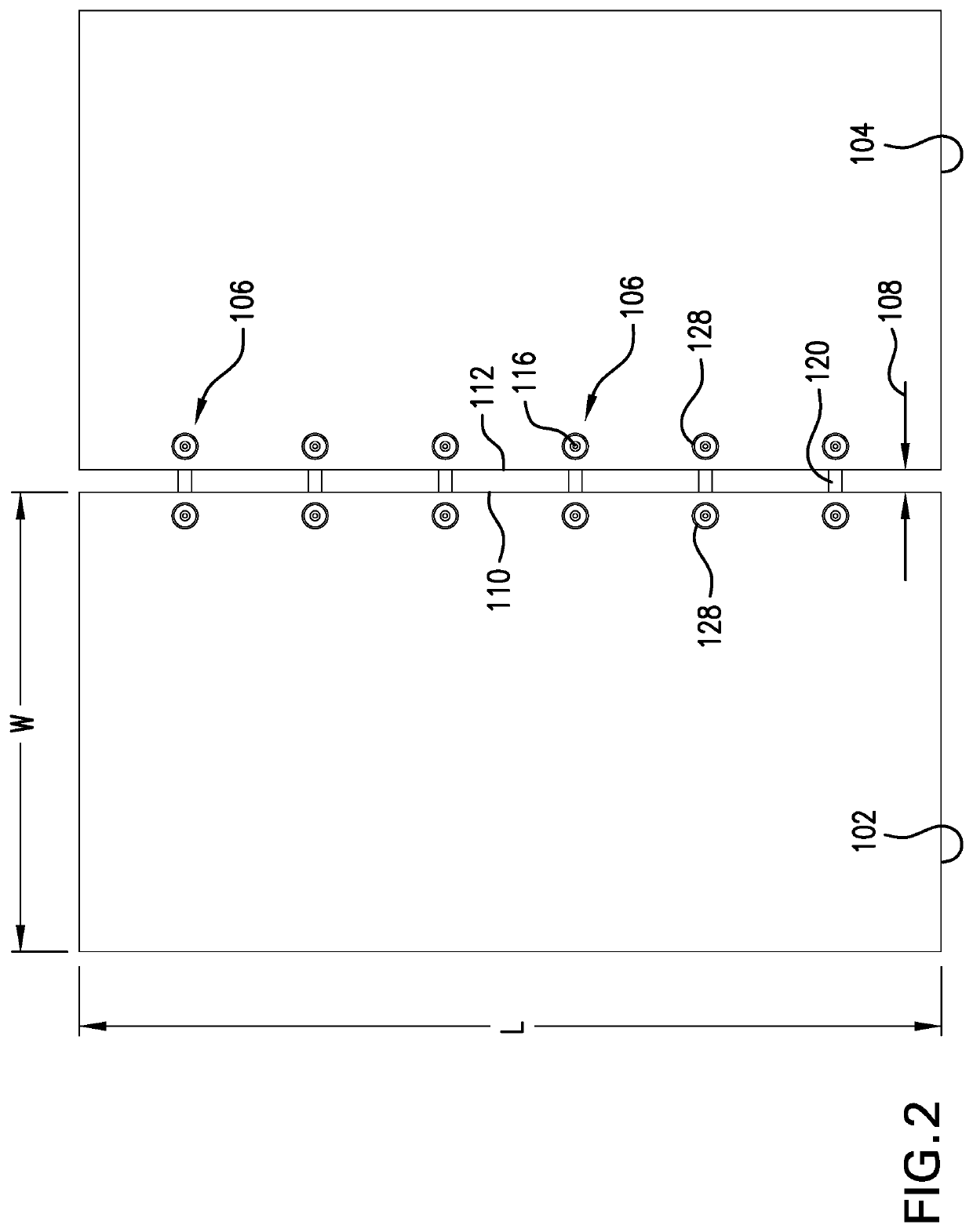
a floor covering system and module technology, applied in the field of floor covering systems, can solve the problems of creating a visual bump on the top of each rug and uneven surface to step, and achieve the effects of reducing the likelihood of a user tripping, reducing installation time and labor costs, and fast and efficient screw connection

Active Publication Date: 2022-04-05
SINAR MAS GROUP
View PDF19 Cites 0 Cited by
  • Summary
  • Abstract
  • Description
  • Claims
  • Application Information

AI Technical Summary

Benefits of technology

The modular rug system in this patent has a plurality of recesses on its top surface to prevent screws from protruding and cause uneven surfaces. These recesses serve as visual guides for technicians to easily connect screws to each rug during installation. This design reduces installation time and labor costs. Additionally, the recesses can be manufactured using different yarns, patterns, or colors to visually distinguish them during installation.

Problems solved by technology

However, the second component of each fastener typically protrudes above the top surface of a rug, creating a visual bump on top of each rug and an uneven surface to step on.

Method used


Image

  • Modular floor covering system
  • Modular floor covering system
  • Modular floor covering system

Examples


Embodiment Construction

[0036]Exemplary embodiments of the present invention will be described more fully hereinafter with reference to the accompanying drawings. The present invention may, however, be embodied in different forms and should not be construed as being limited to the embodiments set forth herein. Like reference numerals may refer to like elements throughout the specification. The sizes and / or proportions of the elements illustrated in the drawings may be exaggerated for clarity. In addition, the dimensions illustrated in the drawings are merely exemplary. The scope of the present invention is not limited thereto.

[0037]When an element is referred to as being disposed on another element, intervening elements may be disposed therebetween. In addition, elements, components, parts, etc., not described in detail with respect to a certain figure or embodiment may be assumed to be similar to or the same as corresponding elements, components, parts, etc., described in other parts of the specification....


PUM

PropertyMeasurementUnit
heightaaaaaaaaaa
widthaaaaaaaaaa
shapeaaaaaaaaaa

Abstract

A modular rug system includes a plurality of rug elements spaced apart from and connected to one another via a plurality of elongated fasteners. Each fastener connects two neighboring rug elements to one another. Each fastener has a first elongated component extending under a pair of neighboring rug elements, a second component disposed on a top surface of one of the pair of neighboring rug elements, and a third component disposed on a top surface of the other of the pair of rug elements. The top surfaces of neighboring rug elements are respectively recessed at defined locations in order to receive the second and third components of the fastener therein.

Description

CROSS-REFERENCE TO RELATED APPLICATIONS[0001]This patent application is a continuation of U.S. non-provisional patent application Ser. No. 17 / 241,180, filed on Apr. 27, 2021, which in turn claims priority under 35 U.S.C. § 119 to U.S. provisional patent application No. 63 / 142,025, filed on Jan. 27, 2021, the disclosures of which are incorporated by reference herein in their entireties.TECHNICAL FIELD[0002]The present invention relates to a floor covering system, and more particularly, to a modular floor covering system that utilizes a plurality of fasteners for connecting a plurality of floor covering components to one another.DISCUSSION OF THE RELATED ART[0003]A modular rug system includes a pair of individual rugs connected to one another by fasteners. The rugs are configured to cover a floor surface area. Fasteners that create a secure connection between the rugs may have a first component extending on the underside of the rugs and a second component disposed over the top surface...

Claims


Application Information

Patent Timeline
Patent Type & Authority Patents(United States)
IPC IPC(8): E04F21/00E04F15/10E04F15/02
CPCE04F21/0092E04F15/02038E04F15/10E04F2201/0523A47G27/025A47G27/0293
Inventor HENDIFAR, GABRIEL
Owner SINAR MAS GROUP
Learn More