
Blade for a turbomachine turbine, comprising internal passages for circulating cooling air

a turbomachine turbine and internal passage technology, applied in the field of blades for turbomachine turbines, can solve the problems of reducing the general performance of the turbomachine, affecting the specific consumption of the turbomachine, and the progress made in the direction of machines/engines, mechanical apparatus, etc., and achieves the effect of simple, economic and efficien

Active Publication Date: 2022-03-29
SN DETUDE & DE CONSTR DE MOTEURS DAVIATION S N E C M A
View PDF24 Cites 0 Cited by
  • Summary
  • Abstract
  • Description
  • Claims
  • Application Information

AI Technical Summary

Benefits of technology

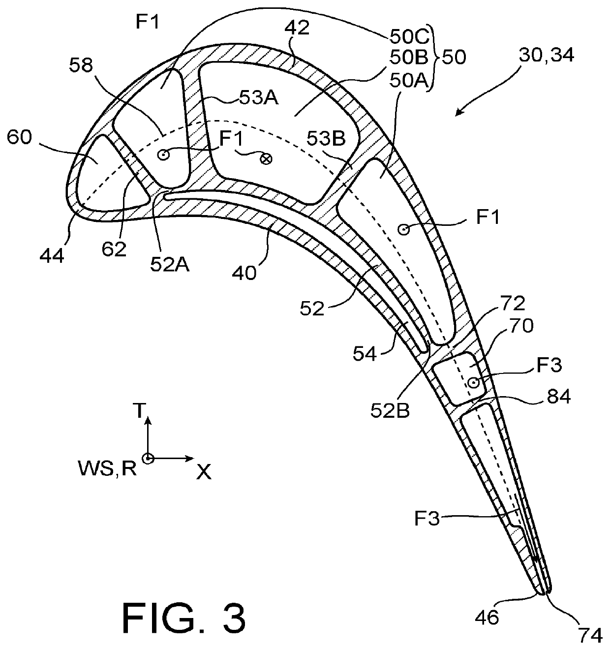
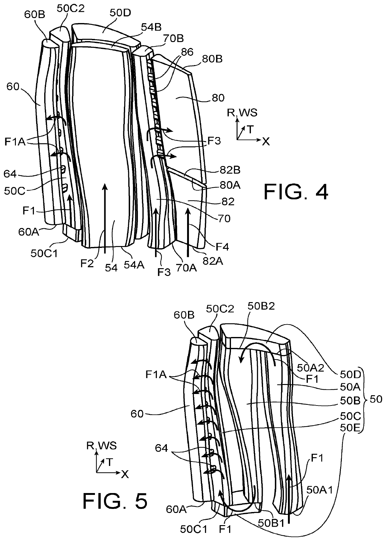
[0014]In use, the main cavity thus enables a main airflow circulating in the same to follow a relatively long path, which makes it possible to maximise heat exchanges between this main airflow and the walls delimiting the main cavity, whereas the side cavity enables a heat shield to be formed between the entire main cavity and the pressure side wall, which is generally particularly hot, so as to limit heating of the main airflow through the pressure side wall. Consequently, the main airflow remains relatively fresh at the outlet of the main cavity and hence can be exploited to cool another portion of the airfoil, as will appear more clearly in what follows.
[0015]The invention thus generally makes it possible to limit the flow rate necessary as regards the main airflow circulating in the main cavity.
[0018]The main airflow circulating in the main cavity thus allows cooling of the suction side wall.
[0023]Thus, the thermal heating of the airflow circulating in the main cavity is limited by the presence of the side cavity which protects the main cavity from the pressure side wall, being relatively hot. Controlling the thermal heating of the airflow circulating in the main cavity and cooling the airfoil walls forming the leading edge through impingement makes it possible to ensure a limited temperature of the airfoil at the leading edge.
[0027]Such a rear airflow, distinct from the main airflow and from the side airflow, can be exploited to cool the region of the airfoil close to the trailing edge.

Problems solved by technology

However, the constant improvement in the aircraft engine performance results in an increase in the temperature of the combustion gases.
But, progress made as regards materials and coatings used to form the blades do not make it possible on their own to compensate for the rise in the temperature of the combustion gases.
Indeed, taking cooling air for the blades at a compressor of the turbomachine (typically the high pressure compressor in the case of a two-spool turbomachine) tends to degrade the general turbomachine performance, in particular in terms of specific consumption.

Method used


Image

  • Blade for a turbomachine turbine, comprising internal passages for circulating cooling air
  • Blade for a turbomachine turbine, comprising internal passages for circulating cooling air
  • Blade for a turbomachine turbine, comprising internal passages for circulating cooling air

Examples


Embodiment Construction

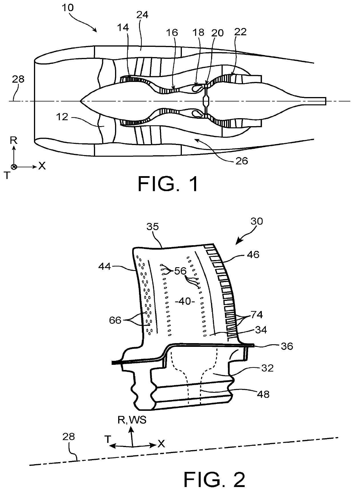
[0041]FIG. 1 illustrates a turbomachine 10 for an aircraft, for example a bypass twin-spool turbofan engine, generally including a fan 12 for sucking an airflow divided downstream of the fan into a primary flow supplying a core of the turbomachine and a secondary flow bypassing this core. The core of the turbomachine generally includes a low pressure compressor 14, a high pressure compressor 16, a combustion chamber 18, a high pressure turbine 20 and a low pressure turbine 22. The turbomachine is shrouded with a nacelle 24 surrounding the secondary flow channel 26. The rotors of the turbomachine are rotatably mounted about a longitudinal axis 28 of the turbomachine.

[0042]In the entire description, the axial direction X is the direction of the longitudinal axis 28 of the turbomachine, the radial direction R is at any point a direction orthogonal to the axial direction X and intersecting the same, and the tangential direction T is at any point orthogonal to both previous directions. O...


PUM


Abstract

In order to limit the air flow required to cool its blade member, a blade for an aircraft turbomachine turbine includes, in its blade member, a main passage configured to collect a main air flow from an air inlet and to circulate it in the blade member, and a side passage located between the main passage and the pressure-side wall, while being separated from the main passage, wherein the side passage is configured to collect a side air flow from the air inlet and to circulate it in the blade member, the main passage having at least three portions connected together end-to-end to form a coil, the side passage being located between each of these portions and the pressure-side wall.

Description

TECHNICAL FIELD[0001]The present invention relates to the field of aircraft turbomachines and more particularly relates to the cooling of the moving blades of the turbines within such turbomachines.STATE OF PRIOR ART[0002]Within a turbomachine used to propel an aircraft, turbine blades are subjected to high heat of the combustion gases from the combustion chamber. It is in particular the case of blades directly arranged at the outlet of the combustion chamber, such as the blades of a high pressure turbine in a multi-spool turbomachine.[0003]To protect the blades from these high temperatures, it is known to cool the blades by means of an airflow circulating in cavities provided inside the airfoils of the blades. These cavities are generally supplied with relatively fresh air taken at a compressor stage of the turbomachine.[0004]Document FR 3 020 402 A1 describes an example of internal configuration of a blade provided with such cavities.[0005]However, the constant improvement in the ...

Claims


Application Information

Patent Timeline
Patent Type & Authority Patents(United States)
IPC IPC(8): F01D5/18F02C7/18
CPCF01D5/186F02C7/18F05D2260/202F01D5/187F05D2240/303F05D2240/304F05D2250/185Y02T50/60
Inventor OSTINO, LEANDREENEAU, PATRICEDUJOL, CHARLOTTE MARIE
Owner SN DETUDE & DE CONSTR DE MOTEURS DAVIATION S N E C M A
Learn More