
Roller blind assembly

a roller blind and assembly technology, applied in the field of roller blind assembly, can solve the problems of large variance between roller blind assembly and actual assembled system, complex installation process, inefficient and/or costly, etc., and achieve the effect of reducing or eliminating the need for on-site calibration, reducing or eliminating the need for installation, and increasing efficiency

Active Publication Date: 2022-03-29
MARZILLI ANTONIO
View PDF9 Cites 0 Cited by
  • Summary
  • Abstract
  • Description
  • Claims
  • Application Information

AI Technical Summary

Benefits of technology

The patent text discusses the issue of individual components in a roller blind system having varying performance, which can result in the actual system performing differently than expected. Manufacturers and assemblers often have to assemble and test each system before sending it out for installation, which decreases efficiency and increases cost. The text also highlights that rotation of the blind roller in different directions can change the torque exerted by the spring on the roller.

Problems solved by technology

As a result, there is significant amount of variance across roller blind assemblies.
These drawbacks are often compounded and can lead to a complex, inefficient, and / or costly installation process.
Accordingly, even if the manufacturer and / or assembler selects appropriate components based on their rated performance, the actual assembled system may not perform as expected.
Accordingly, manufacturers and / or assemblers often need to assemble and test each roller blind system (and substitute components as needed if the performance of the assembled system is unacceptable) before sending it out to be installed.
This may result in decreased efficiency and / or increased cost.
As a result, if a system is not correctly calibrated during the initial installation, the installer (or another technician) may need to make one or more return visits to the installation site.
This may result in increased efficiency and / or decreased cost as compared to known roller blind systems.

Method used


Image

  • Roller blind assembly
  • Roller blind assembly
  • Roller blind assembly

Examples


Embodiment Construction

[0098]Various apparatuses, methods and compositions are described below to provide an example of an embodiment of each claimed invention. No embodiment described below limits any claimed invention and any claimed invention may cover apparatuses and methods that differ from those described below. The claimed inventions are not limited to apparatuses, methods and compositions having all of the features of any one apparatus, method or composition described below or to features common to multiple or all of the apparatuses, methods or compositions described below. It is possible that an apparatus, method or composition described below is not an embodiment of any claimed invention. Any invention disclosed in an apparatus, method or composition described below that is not claimed in this document may be the subject matter of another protective instrument, for example, a continuing patent application, and the applicant(s), inventor(s) and / or owner(s) do not intend to abandon, disclaim, or d...


PUM


Abstract

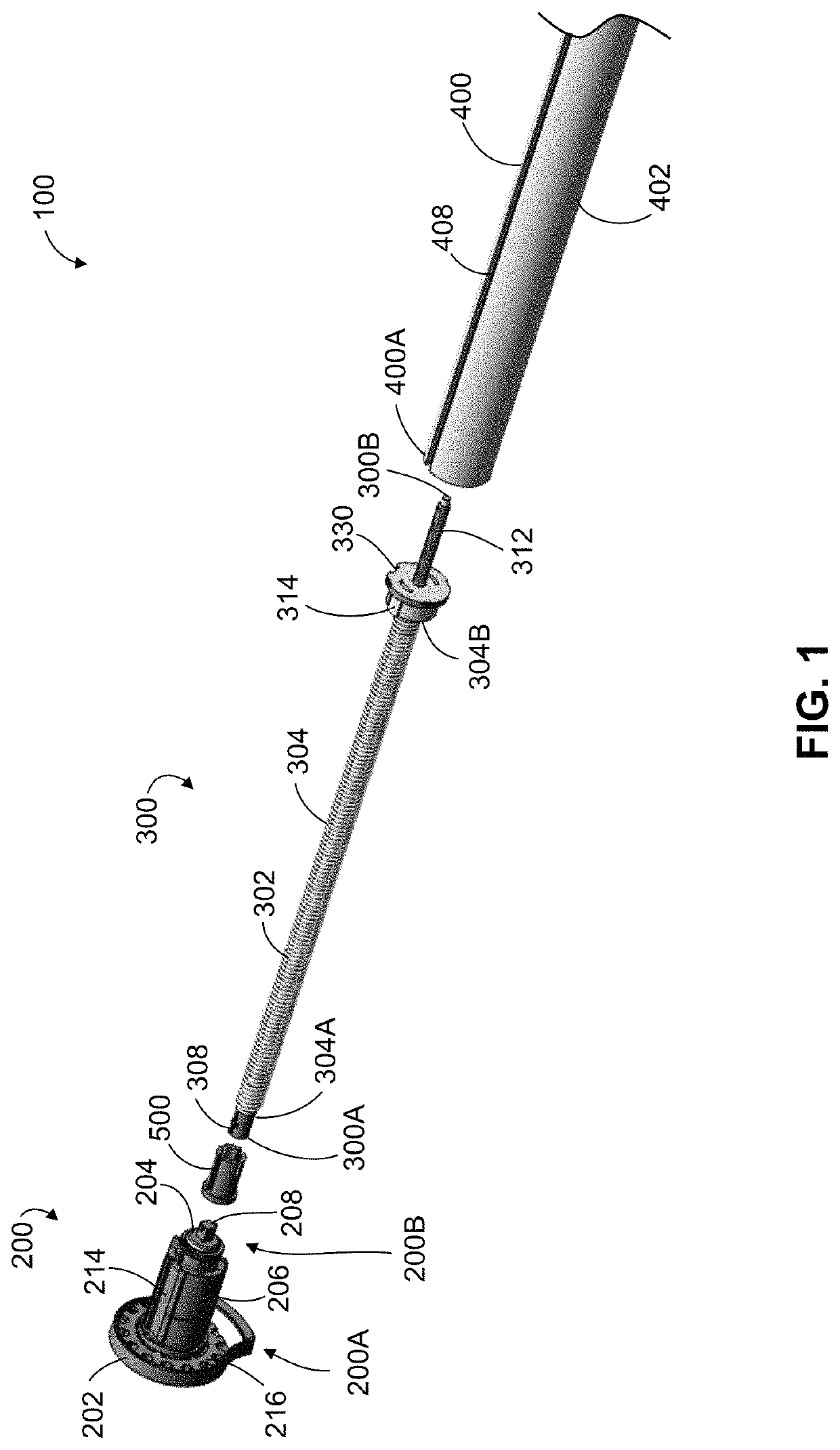
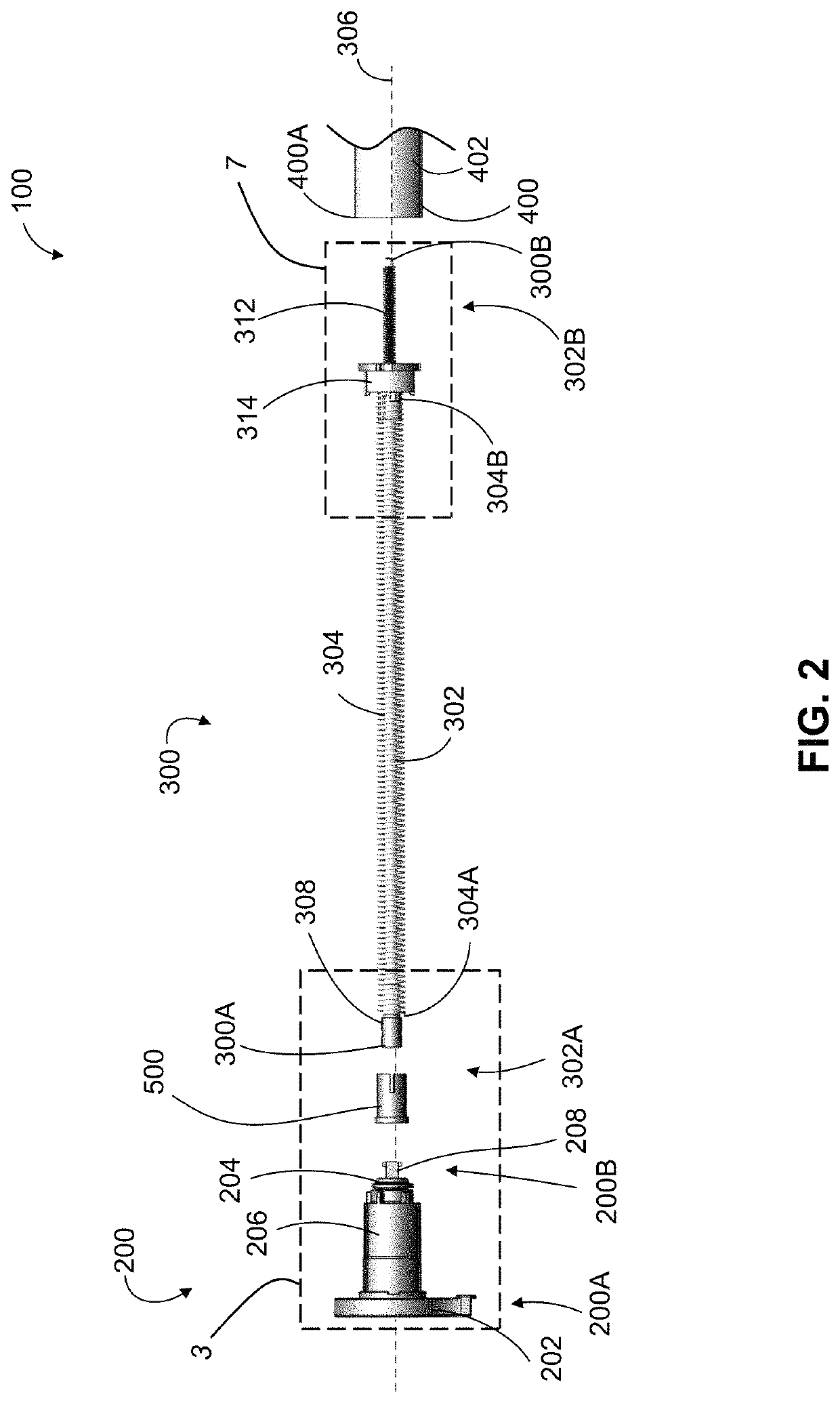
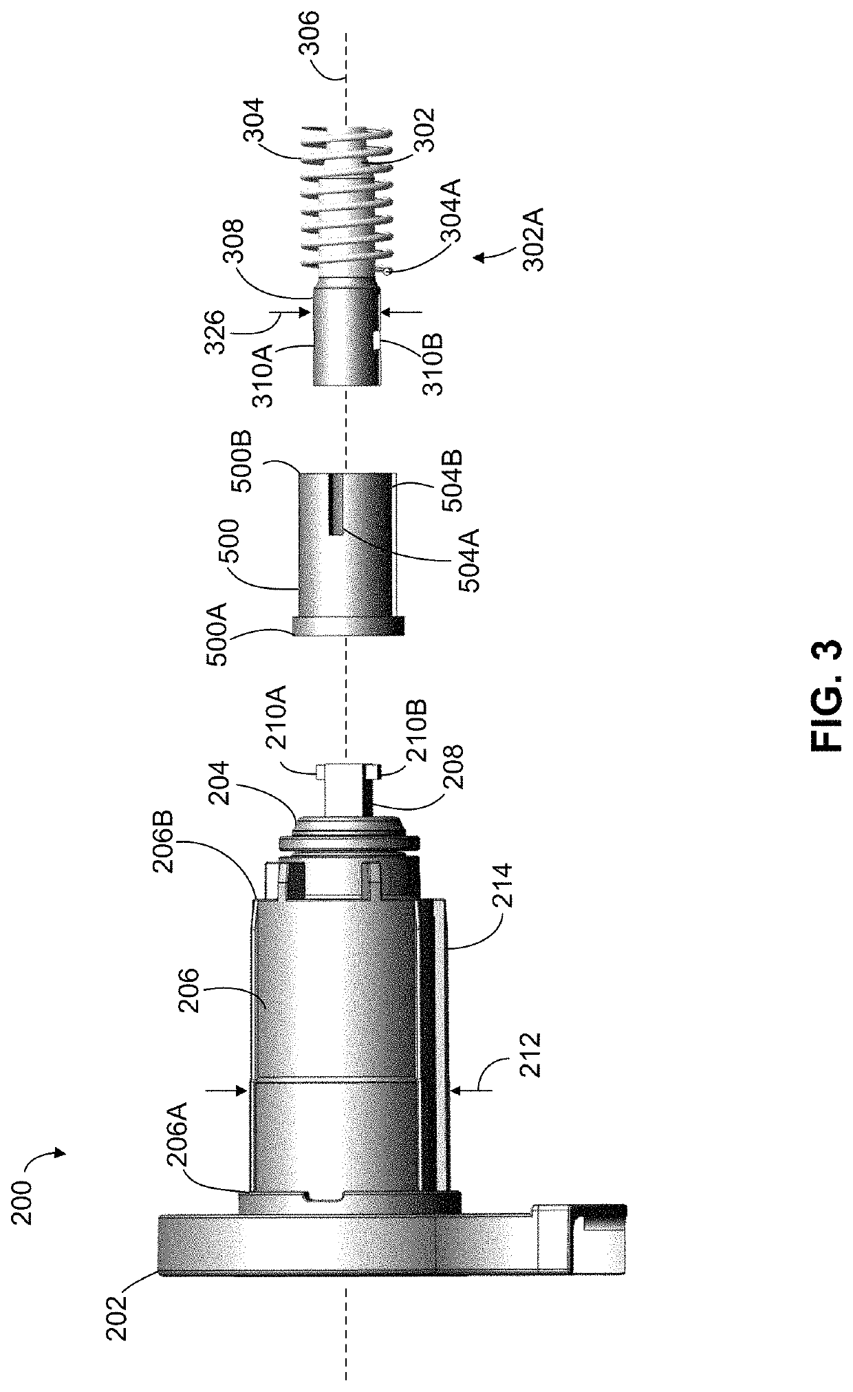
A roller blind assembly includes a blind roller, a clutch assembly that includes a bracket engagement member, and a pre-torsioned spring assembly that includes a spring. The pre-torsioned spring assembly is positioned in an interior cavity of the blind roller, and exerts a torque proportional to a preset torsion of the spring to promote rotation of the blind roller relative to the bracket engagement member. Rotation of the blind roller relative to the bracket engagement member in a first direction decreases torsion in the spring while rotation of the blind roller relative to the bracket engagement member in a second direction increases torsion in the spring. The pre-torsioned spring assembly is preferably selected from a group of at least two pre-torsioned spring assemblies, each spring assembly having a different spring preset torsion.

Description

CROSS-REFERENCE TO RELATED APPLICATIONS[0001]This application claims the benefit of U.S. Provisional Application No. 62 / 889,345 filed on Aug. 20, 2019, which is incorporated by reference herein in its entirety.FIELD OF THE INVENTION[0002]This application relates generally to apparatus for supporting blind rollers, and more specifically to roller blind assemblies that include a pre-torsioned spring assembly selected from at least two pre-torsioned spring assemblies.INTRODUCTION[0003]Roller blinds are well known. Such blinds are commonly used, for example, to selectively control the passage of light through openings (e.g. windows, glass doors, and the like) in residential, commercial, and industrial buildings.[0004]It is known to provide roller blind assemblies with some form of ‘spring-assist’ in which a spring (or other biasing member) is provided to urge the blind roller towards a raised position in an effort to at least partially offset the weight of blind material hanging from th...

Claims


Application Information

Patent Timeline
Patent Type & Authority Patents(United States)
IPC IPC(8): E06B9/42E06B9/60E06B9/80
CPCE06B9/42E06B9/60E06B9/80E06B2009/801E06B9/90
Inventor MARZILLI, ANTONIO
Owner MARZILLI ANTONIO
Learn More