
Systems and methods for sensing, recording, analyzing and reporting environmental conditions in data centers and similar facilities

a data center and environmental monitoring technology, applied in the direction of electrical apparatus construction details, instruments, using reradiation, etc., can solve the problems of data center construction and maintenance costs that are typically high, data center data center maintenance costs are typically high, and the computer aided design (cad) drawings used for asset management are constantly out of date, so as to improve the performance of major support infrastructure assets, improve the efficiency of equipment, and create flexibility

Active Publication Date: 2022-03-22
ETA VISION INC
View PDF106 Cites 6 Cited by
  • Summary
  • Abstract
  • Description
  • Claims
  • Application Information

AI Technical Summary

Benefits of technology

The present invention is about creating more flexibility and performance in data centers by using sensor data to track and manage important assets. This allows data center operators to improve infrastructure management, reduce costs, and comply with regulations. In simple terms, the invention helps keep track of and manage valuable data center assets.

Problems solved by technology

Data centers typically cost a substantial amount to build and maintain.
Part of the cost is the enormous amount of electricity data centers need to run properly.
Unfortunately, Computer Aided Design (CAD) drawings used for asset management are constantly out of date due to frequent upgrades and / or changes to the arrangement of equipment inside a data center.
This increased utilization may produce significantly more heat in the physical space that the processors occupy.
This can drive up overall operating costs.
Over time, incremental changes to the computing and / or power demands may increase the demands on the support infrastructure until the support infrastructure is no longer adequate to safely support the operation of the computing equipment.
In some cases, IT changes can be so significant that the environmental conditions push elements of the IT equipment into fault tolerances and can put quality of service at risk.

Method used


Image

  • Systems and methods for sensing, recording, analyzing and reporting environmental conditions in data centers and similar facilities
  • Systems and methods for sensing, recording, analyzing and reporting environmental conditions in data centers and similar facilities
  • Systems and methods for sensing, recording, analyzing and reporting environmental conditions in data centers and similar facilities

Examples


Embodiment Construction

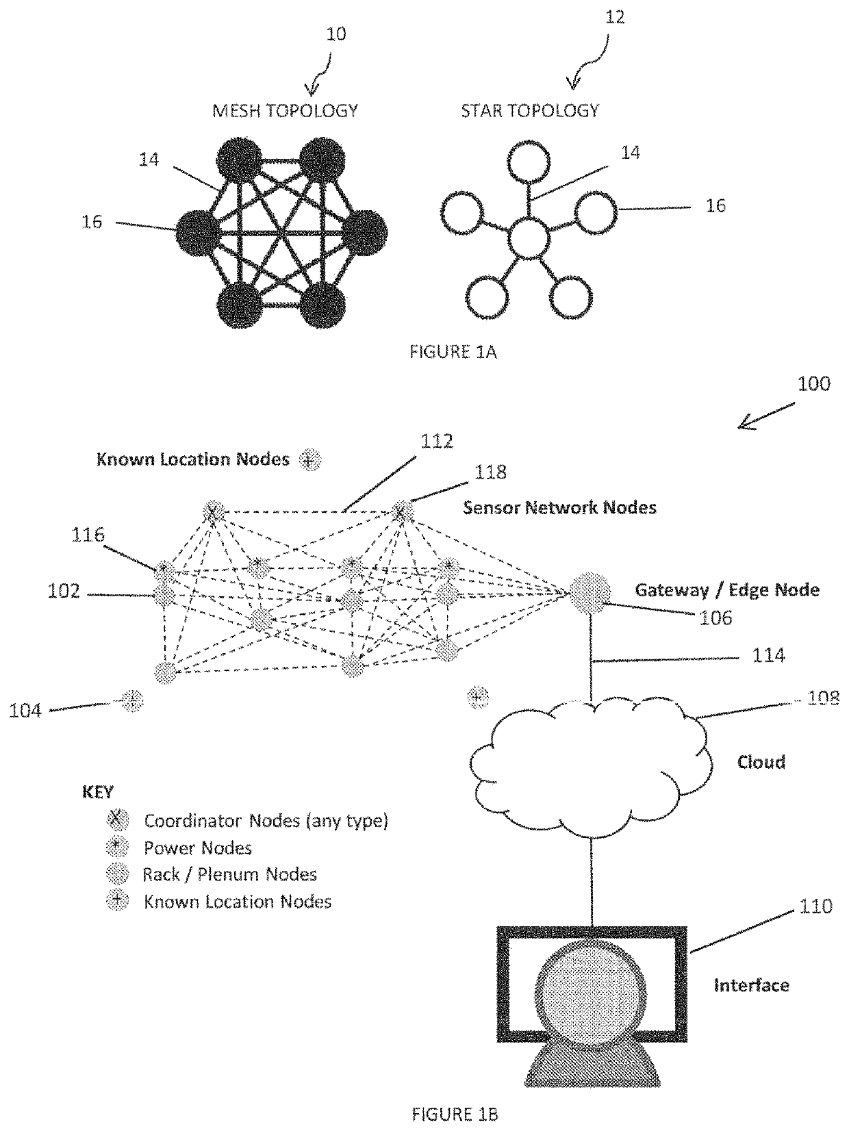
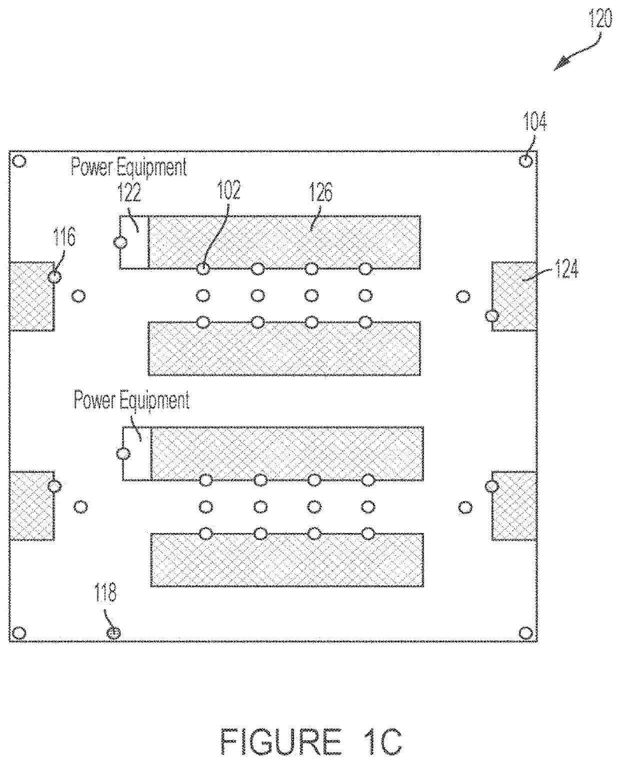
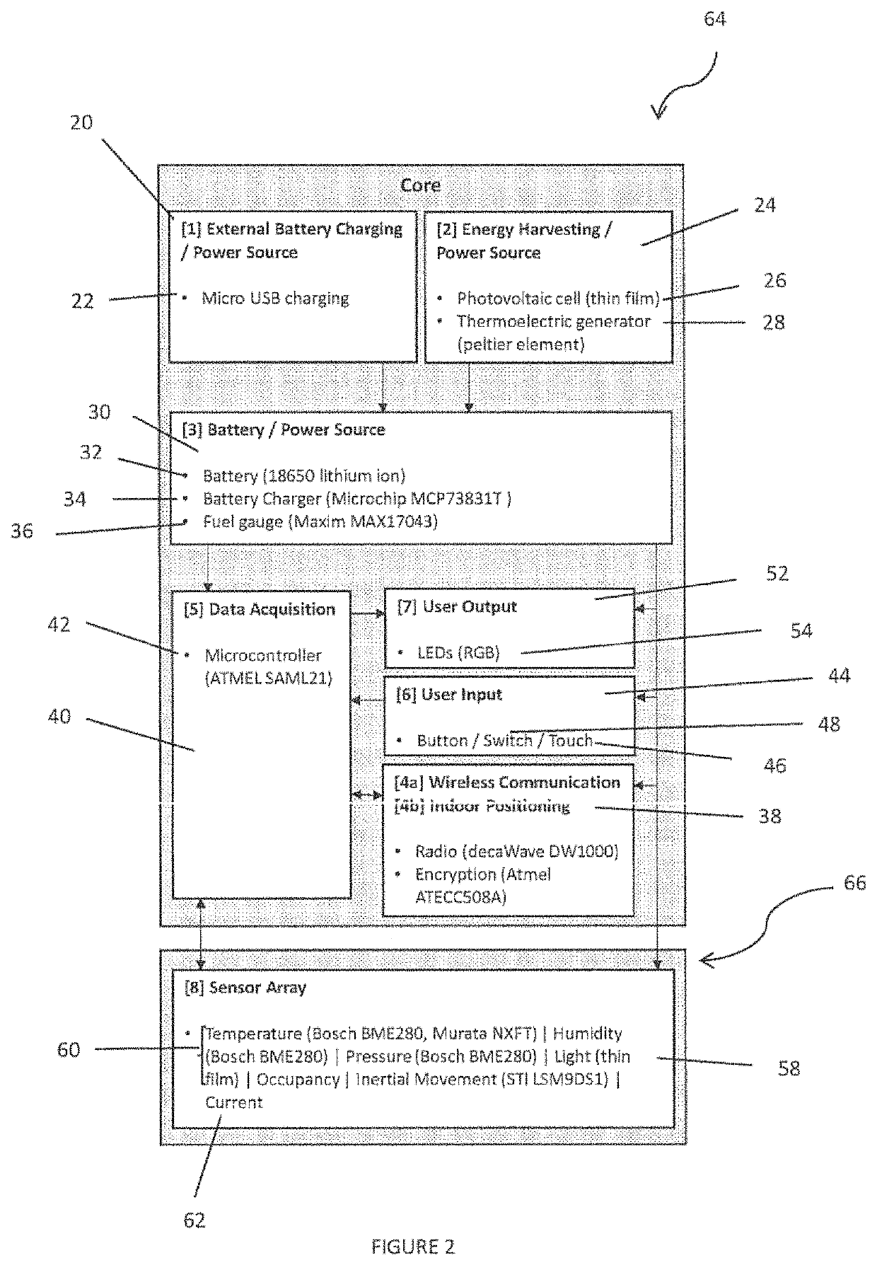
[0062]Some examples of the present disclosure may relate to a system, comprising a sensor system configured to mount to a server rack within a data center, the sensor system comprising a sensor configured to measure data within the data center, a computing system configured to receive the data, the computing system comprising processing circuitry, and memory circuitry comprising machine readable instructions which, when executed, cause the processing circuitry to determine a position of the sensor within the data center, determine an efficiency indicator based on the data measured by the sensor and the position of the sensor, determine whether there is an inefficiency within the data center based on the efficiency indicator, and in response to determining there is an inefficiency, recommend a solution to the inefficiency.

[0063]In some examples, the sensor comprises a first sensor, the sensor system further comprises a second sensor configured to measure data within the data center, ...


PUM


Abstract

The present disclosure pertains to utilizing hardware and software to control and record environmental and other data obtained from sensors and other devices, placed throughout a facility, and analyzing and displaying the information in a detailed status report of the environmental conditions inside facility, and once analyzed, the software can provide recommendations to implement measures that increase the efficiency of the facility.

Description

CROSS-REFERENCE TO RELATED APPLICATIONS[0001]This application is a continuation-in-part of U.S. patent application Ser. No. 16 / 383,216, filed on Apr. 12, 2019, entitled “SYSTEMS AND METHODS FOR SENSING, RECORDING, ANALYZING AND REPORTING ENVIRONMENTAL CONDITIONS IN DATA CENTERS AND SIMILAR FACILITIES,” which is a continuation-in-part of U.S. patent application Ser. No. 15 / 369,537, filed on Dec. 5, 2016, entitled “SYSTEMS AND METHODS FOR SENSING, RECORDING, ANALYZING AND REPORTING ENVIRONMENTAL CONDITIONS IN DATA CENTERS AND SIMILAR FACILITIES,” which claimed priority to U.S. provisional application No. 62 / 262,715, filed Dec. 3, 2015, entitled SYSTEMS AND METHODS FOR SENSING, RECORDING, ANALYZING AND REPORTING ENVIRONMENTAL CONDITIONS IN DATA CENTERS AND SIMILAR FACILITIES, all of which are hereby incorporated by reference in their entirety as though fully set forth herein.TECHNICAL FIELD[0002]The present disclosure pertains to sensing, measuring, recording, and reporting environment...

Claims


Application Information

Patent Timeline
Patent Type & Authority Patents(United States)
IPC IPC(8): G06F15/173H05K7/20G06Q10/06G06F11/30
CPCH05K7/20836G06F11/3062G06Q10/06315G01S5/0036G01S5/017G01S5/02585G01S5/02695G01S5/14G01S7/006G01S13/0209G01S13/765G01S13/876G01S2205/02H04W4/029H04W4/33H04W4/38G06F11/3058G06F11/3006H04L67/12
Inventor LINGLE, MIKECONABOY, MICHAELBOEHNKE, PATRICK
Owner ETA VISION INC
Learn More