
Resilient dynamic projection mapping system and methods

a dynamic projection mapping and dynamic projection technology, applied in image analysis, image enhancement, instruments, etc., can solve the problems of limiting the type and size of objects tracked and rendered by such systems, and limiting the scalability of prior projection mapping systems. achieve the effect of confirming validity and reducing processing load on computing devices

Active Publication Date: 2022-03-08
NIKE INC
View PDF2 Cites 2 Cited by
  • Summary
  • Abstract
  • Description
  • Claims
  • Application Information

AI Technical Summary

Benefits of technology

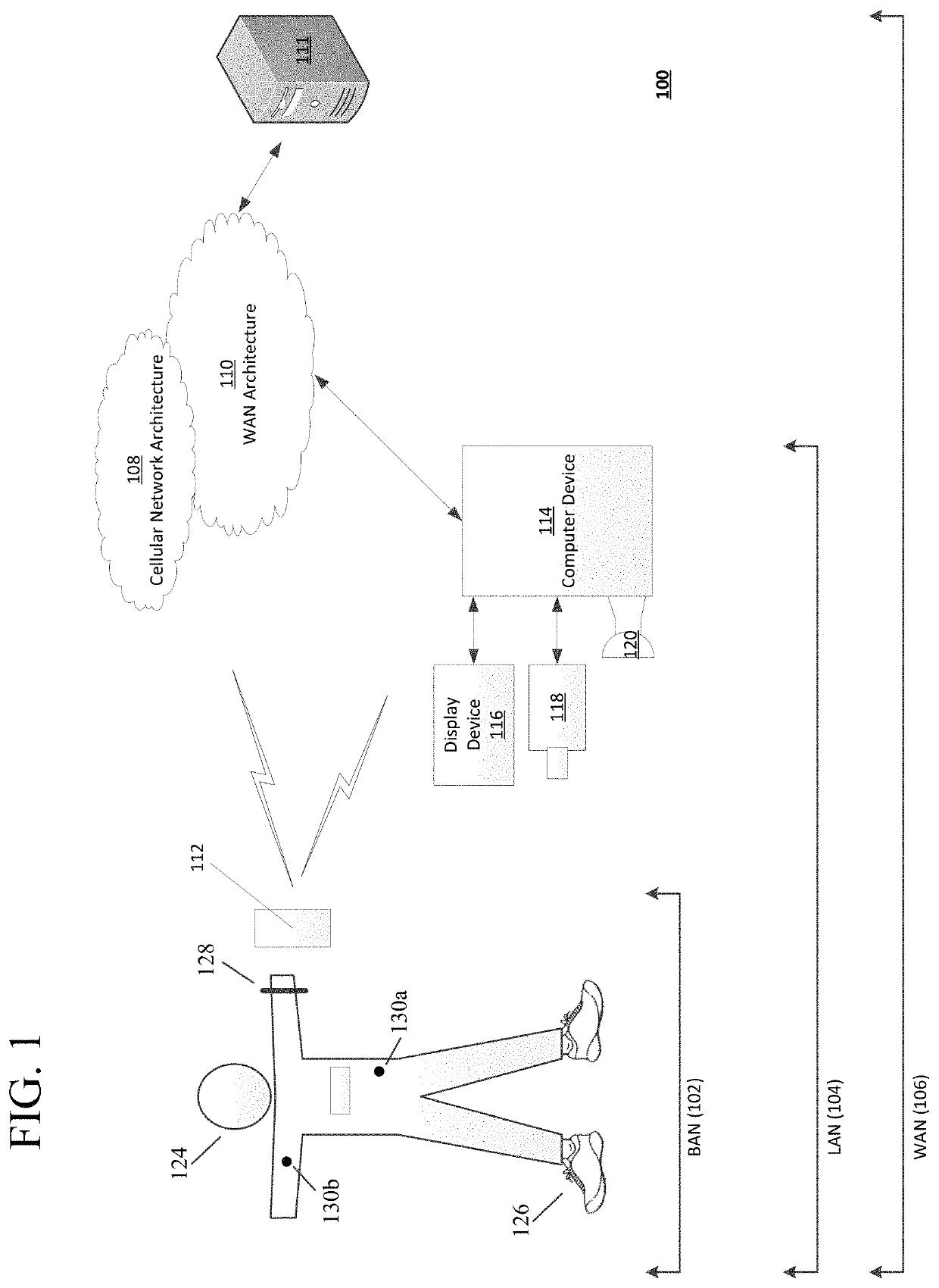
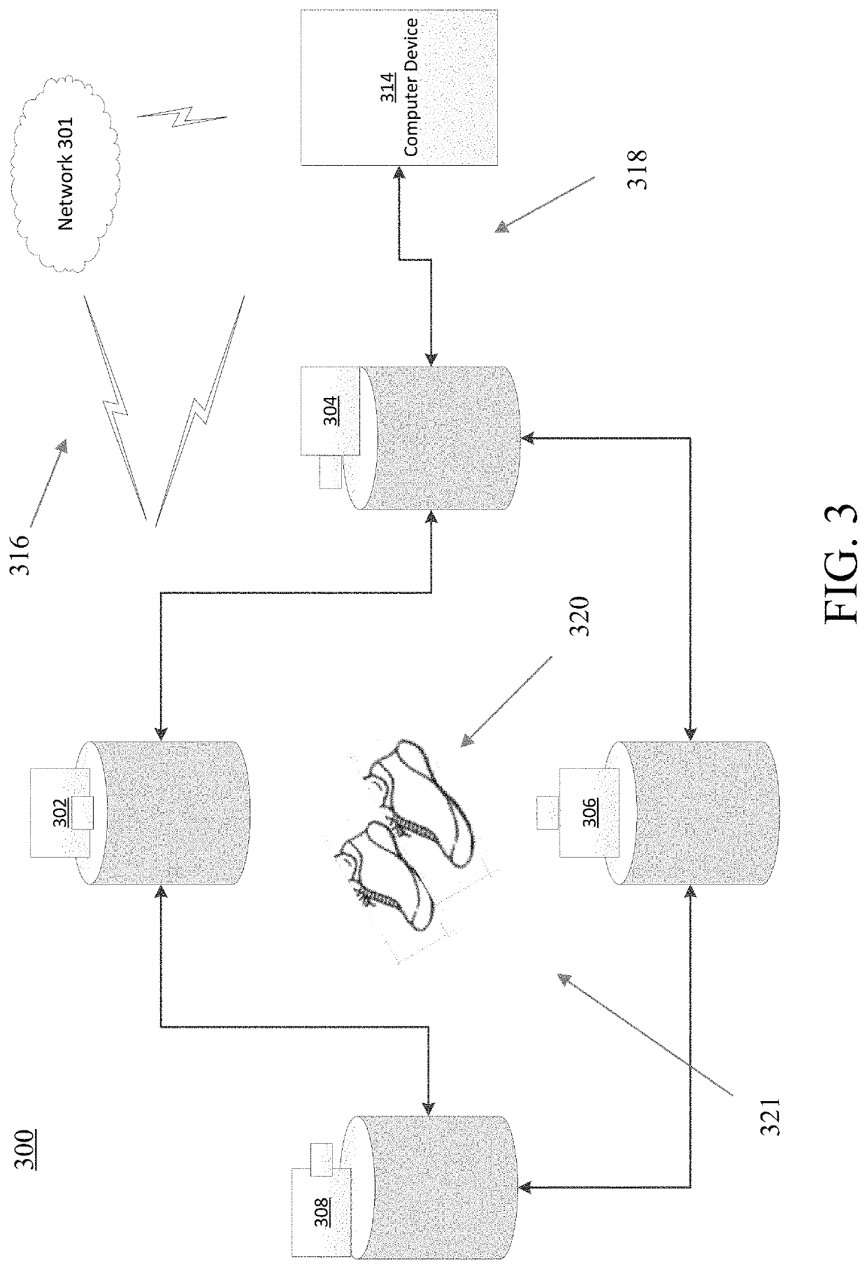
[0006]Aspects of this disclosure relate to improving systems and methods for dynamically tracking physical objects and projecting, in real-time, rendered 3D content onto said physical objects. Certain implementations may reduce the processing load on computing devices used to track physical objects and render 3D content thereon. In some embodiments, image data captured by various image-capturing devices may be segmented into various components such that the system may identify the best (e.g., optimal) projection devices for rendering and projecting each component of 3D content onto the physical object. Additionally, the projection system described herein performs contour detection of image data indicating the physical object, thereby enabling the system to track the position / angle of the physical object (in real-time) and, further, to filter out “false positives” in physical object detection by tracking detected contours for a specified time period to confirm their validity.

Problems solved by technology

Certain projection mapping systems are limited in terms of the type of physical objects that may be used to project content thereon, and further, the system's ability to accurately track physical objects and render content onto those objects in real-time.
Performing such resource-intensive object tracking and content rendering limits the scalability of prior projection mapping systems and, further, limits the type and size of the objects that are tracked and rendered by such systems.

Method used


Image

  • Resilient dynamic projection mapping system and methods
  • Resilient dynamic projection mapping system and methods
  • Resilient dynamic projection mapping system and methods

Examples


Embodiment Construction

[0017]Aspects of innovations disclosed herein further relate to systems and methods for dynamically tracking physical objects in a coordinate space and, further, rending and projecting content onto said objects using position and rotation angle information collected from image-capturing devices. Using improved processing, tracking, and rendering techniques, the projection mapping system described herein may selectively and dynamically identify the optimal projection devices for rendering and projecting content onto physical objects in real-time.

[0018]In the following description of the various embodiments, reference is made to the accompanying drawings, which form a part hereof, and in which is shown by way of illustration various embodiments in which aspects of the disclosure may be practiced. It is to be understood that other embodiments may be utilized and structural and functional modifications may be made without departing from the scope and spirit of the present disclosure. Fu...


PUM


Abstract

Systems and methods for dynamically tracking objects, and projecting rendered 3D content onto said objects in real-time. The methods described herein further include image data capture performed by various image-capturing devices, wherein said data is segmented into various components to identify one or more projectors for rendering and projecting 3D content components onto one or more objects.

Description

[0001]The present application claims the benefit of and priority to U.S. Provisional Patent Application No. 62 / 784,960, entitled “RESILIENT DYNAMIC PROJECTION MAPPING SYSTEM AND METHODS” and filed Dec. 26, 2018, the contents of which is expressly incorporated by reference herein in its entirety for any and all non-limiting purposes.BACKGROUND[0002]Certain projection mapping systems are limited in terms of the type of physical objects that may be used to project content thereon, and further, the system's ability to accurately track physical objects and render content onto those objects in real-time. Indeed, previous projection systems, including those that use marker-based methods for tracking objects, require more processing needs, increased set-up time for pre-scanning objects (e.g., objects fixed with dot markers), and image capturing devices with high fidelity and / or frame rates to capture the marked objects. Performing such resource-intensive object tracking and content renderin...

Claims


Application Information

Patent Timeline
Patent Type & Authority Patents(United States)
IPC IPC(8): G06T1/00G06T7/246G01B11/25G06T17/20
CPCG06T7/251G01B11/2504G06T17/20G06T2207/10028G06T7/246
Inventor LEGAYE, ROBERT G.COYLE, IANLEBLANC, IANPURDY, BENWESTER, THOMAS
Owner NIKE INC
Learn More