Ball socket for a ball joint

a ball joint and ball socket technology, applied in the direction of shafts and bearings, rotary machine parts, bearings, etc., to achieve the effect of tear of the projection and reducing the risk of wear

Active Publication Date: 2022-02-22
ZF FRIEDRICHSHAFEN AG
View PDF21 Cites 2 Cited by
  • Summary
  • Abstract
  • Description
  • Claims
  • Application Information

AI Technical Summary

Benefits of technology

[0014]According to a further development the ball socket body has an outer circumferential surface, in particular extending around the longitudinal axis. Preferably, the ball socket body halves each have an outer circumferential surface corresponding to half of the outer circumferential surface, which extends in particular around the longitudinal axis. Preferably, the first ball socket body half has a first one of the outer circumferential surface halves, which in particular is closed in the circumferential direction. Preferably, the second ball socket body half has a second one of the outer circumferential surface halves, which in particular is closed in the circumferential direction, or closed apart from the slot. Advantageously, the second outer circumferential surface half is convex. Preferably, in particular at or at least an axial distance away from the transition zone, the second outer circumferential surface half has an outer circumferential surface distance away from the mid-point of the spherical surface which is larger than the distance of the first outer circumferential surface half in the transition zone from the mid-point of the spherical surface. For example, the slot width is constant in the direction of the longitudinal axis. In that case, for example, the outer circumferential surface distance of the second outer circumferential surface half is also constant in the direction of the longitudinal axis. In a variant, however, the outer circumferential surface distance of the second outer circumferential surface half varies in the direction of the longitudinal axis. Alternatively, for example the slot width varies in the direction of the longitudinal axis. In that case, in particular the outer circumferential surface distance of the second outer circumferential surface half also varies, preferably as a function of and / or proportionally to the slot width. Preferably the, or the respective outer circumferential surface distance of the second outer circumferential surface half, for example at or in the area of the ball socket opening, is larger by an amount and / or a length difference that depends on the, or the respective slot width than the distance of the first outer circumferential surface half in the transition zone from the mid-point of the spherical surface. In this way it can in particular be ensured that when the ball socket is fitted into the joint housing, the second ball socket body half will be deformed by the pressure of the ball socket against the counterface to an extent sufficient for the second inside peripheral surface half to lie against the ball surface and / or for the slot to be closed.
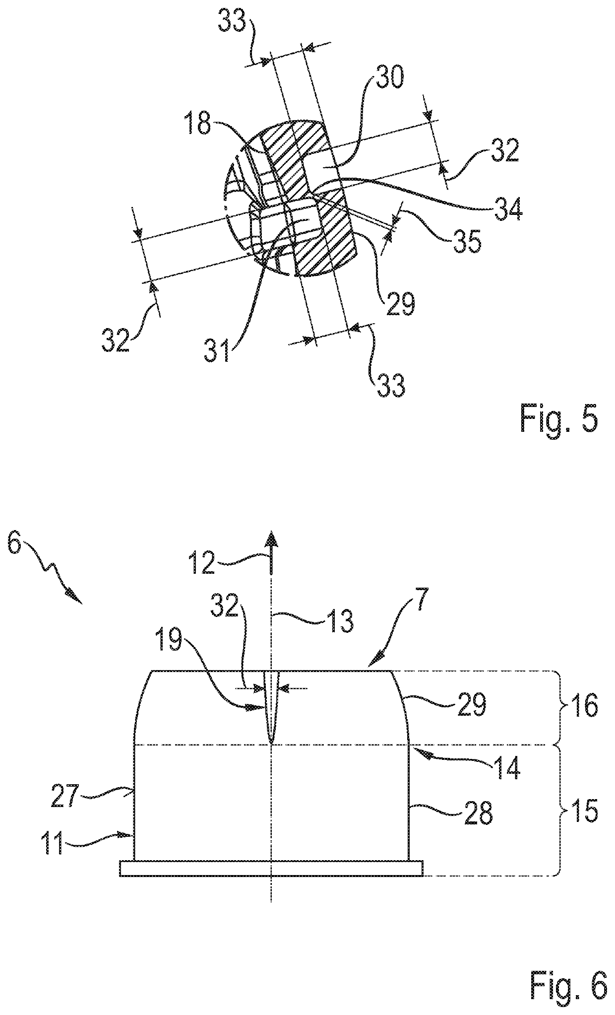
[0018]In the circumferential direction the slot has, in particular, a slot width or the slot width. For example, the slot width is constant, preferably in the direction of the longitudinal axis. With a constant slot width, however, particularly in the direction of the longitudinal axis, complete closing of the slot when fitting the ball socket into the joint housing can be made more difficult. Preferably the slot width of the slot tapers, preferably steadily, particularly in the direction of the longitudinal axis, starting from the ball socket opening in the direction toward the transition zone and / or as far as the transition zone. This measure can in particular facilitate and / or ensure that the slot is closed completely when the ball socket is fitted into the joint housing. For example, at the end of the slot and / or in the transition zone the slot width of the slot is reduced to zero or approximately zero.
[0024]In one embodiment the slot is of stepped form in the, or in a radial direction relative to the mid-point of the spherical surface and / or in the, or in a direction transverse to the longitudinal axis. In that case the slot is formed in the injection-molding die in particular by two projections of the injection-molding die arranged opposite but offset from one another. Thus the projections can be made shorter, which reduces the risk of wearing down the projection. For example, the length of the projections corresponds in each case to half the slot depth and / or half the thickness of the wall in the area of the slot. Preferably however, the projections are shorter than half the slot depth and / or half the wall thickness in the area of the slot, so that after injection molding the skin, or a skin remains. In particular the skin is thinner than half the slot width and / or half the wall thickness in the area of the slot. When releasing the ball socket and / or the ball socket body from the injection-molding die, the skin preferably splits, so that after the release the slot is in particular not closed by the skin.

Problems solved by technology

In the course of wear tests, however, it has been found that under high loads, for example at surface pressures in excess of 130 MPa, the material of the ball socket flows into the area of the slot.
This is undesirable, since thereby the geometry of the ball socket and hence the preset bearing properties of the ball joint are changed.

Method used


Image

  • Ball socket for a ball joint
  • Ball socket for a ball joint
  • Ball socket for a ball joint

Examples


Embodiment Construction

[0039]FIG. 1 shows a sectioned view of a ball joint 1, which comprises a joint housing 3 with a housing opening 2 and a ball stud 5 with a joint ball 4, which with its joint ball is fitted into the joint housing 3 with a ball socket 6 interposed and which extends out of the housing through the housing opening 2. The joint ball 4 sits inside the ball socket 6, which has a ball socket opening 7 through which the ball stud 5 extends out of the ball socket 6. Furthermore, the ball socket 6 has an inside peripheral surface 8 against which the joint ball 4 rests and can move by sliding. In the assembled condition of the ball socket 6 shown in FIG. 1 the inside peripheral surface 8 as a whole lies on a spherical surface 9, which in the fitted condition of the ball joint 1 coincides with the surface of the joint ball 4.

[0040]FIG. 2 shows a perspective representation of the ball socket 6 before it is fitted into the joint housing 3, whereas FIG. 3 shows a view of the ball socket 6 from above...


PUM

PropertyMeasurementUnit
surface pressuresaaaaaaaaaa
axial distanceaaaaaaaaaa
thicknessaaaaaaaaaa

Abstract

A socket for a ball joint having a socket body with an opening and a hollow space, which comprises a concave inside peripheral surface that delimits the hollow space and extends around a longitudinal axis, and which is axially divided into two body halves which merge together in a transition zone, each of which comprises an inside peripheral surface half. A first body half comprises a first inside peripheral surface half which lies on a spherical surface and is closed, in the circumferential direction, and a second body half which comprises the socket opening, at least one slot extending axially and a second inside peripheral surface half which is closed in the circumferential direction, or closed apart from the slot. The second body half is designed such that the second inside peripheral surface half lies outside the spherical surface at least an axial distance away from the transition zone.

Description

[0001]This application is a National Stage completion of PCT / EP2017 / 077078 filed Oct. 24, 2017, which claims priority from German patent application serial no. 10 2016 224 045.5 filed Dec. 2, 2016.FIELD OF THE INVENTION[0002]The invention relates to a ball socket for a ball joint, having a ball socket body comprising a ball socket opening and a hollow space, which has a concave inside peripheral surface that delimits the hollow space and extends around a longitudinal axis orientated in an axial direction, and is divided along the longitudinal axis into two ball socket body halves arranged one behind the other, which merge into one another in a transition zone, each of which has an inside peripheral surface half of the inside peripheral surface that extends around the longitudinal axis, wherein a first one of the ball socket body halves contains a first one of the inside peripheral surface halves, which lies on a spherical surface and is closed in the circumferential direction, and a...

Claims


Application Information

Patent Timeline
Patent Type & Authority Patents(United States)
IPC IPC(8): F16C11/06
CPCF16C11/0638F16C2240/40F16C2240/60F16C2240/70F16C2220/04
Inventor RICHTER, THOMASPRINS, HANS
Owner ZF FRIEDRICHSHAFEN AG
Why Eureka
Try Eureka