
Prosthetic suspension mounting assembly

a technology of suspension and mounting assembly, applied in the field of prosthetics, can solve the problems of extraneous pivoting, rotation and shift during ambulation, and achieve the effect of easy adjustment of the prosthesis to compensa

Active Publication Date: 2022-02-22
KISS TECH LLC
View PDF6 Cites 1 Cited by
  • Summary
  • Abstract
  • Description
  • Claims
  • Application Information

AI Technical Summary

Benefits of technology

The patent describes a spinal implant system that uses a flat head bolt and a centering cup recess to create a secure and flexible attachment for the spinal implant. This design reduces the likelihood of damage to the spine and allows for easy adjustment of the implant position as needed. The system also includes straps and fasteners that prevent lateral shift and rotation, making the implant more stable and secure. Overall, this design provides a safer and more effective spinal implant system.

Problems solved by technology

Stability is a common problem as many existing anchoring systems use a single attachment point to hold the residual limb in place, and this typically leads to extraneous pivoting, rotation and shift during ambulation.

Method used


Image

  • Prosthetic suspension mounting assembly
  • Prosthetic suspension mounting assembly
  • Prosthetic suspension mounting assembly

Examples


Embodiment Construction

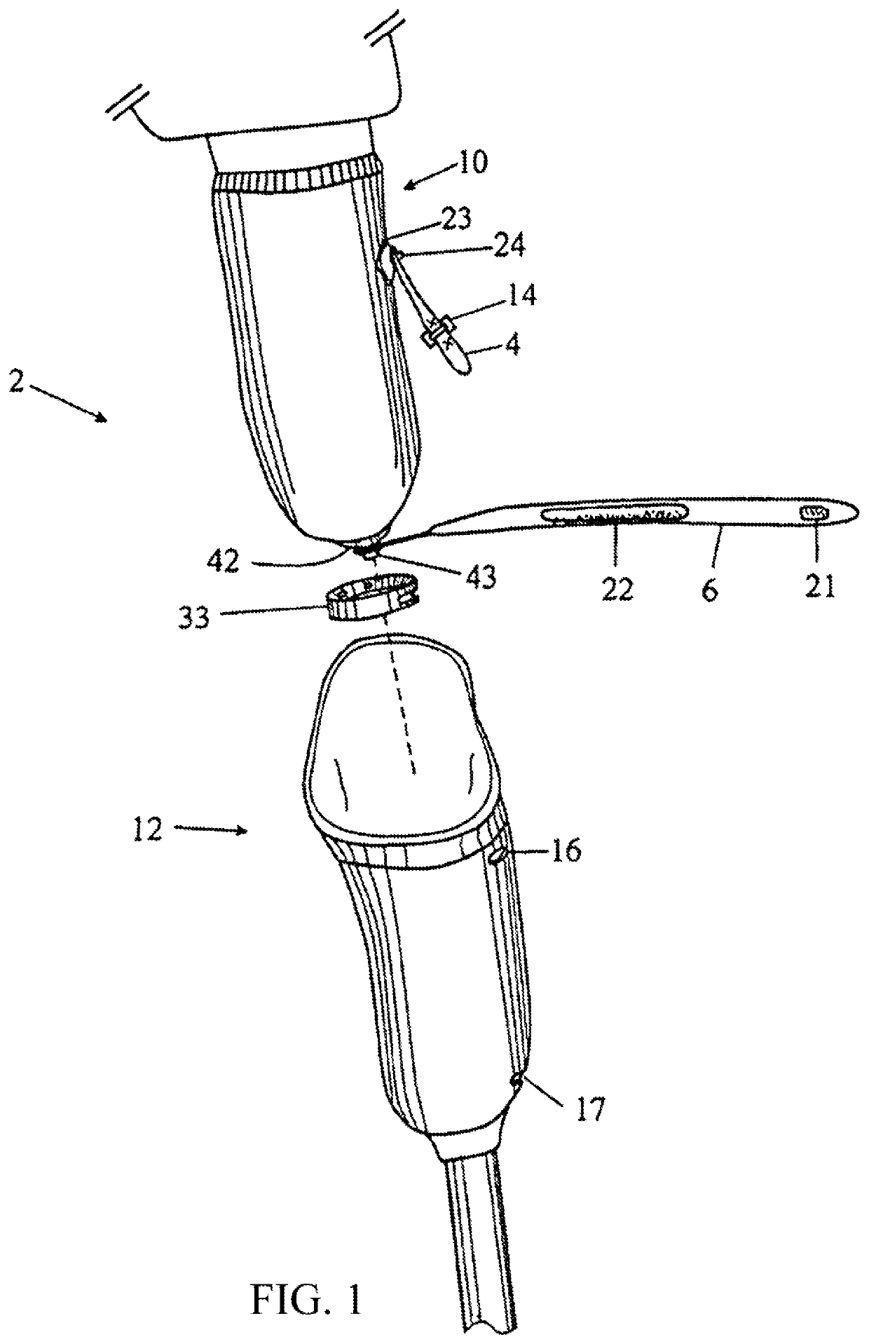
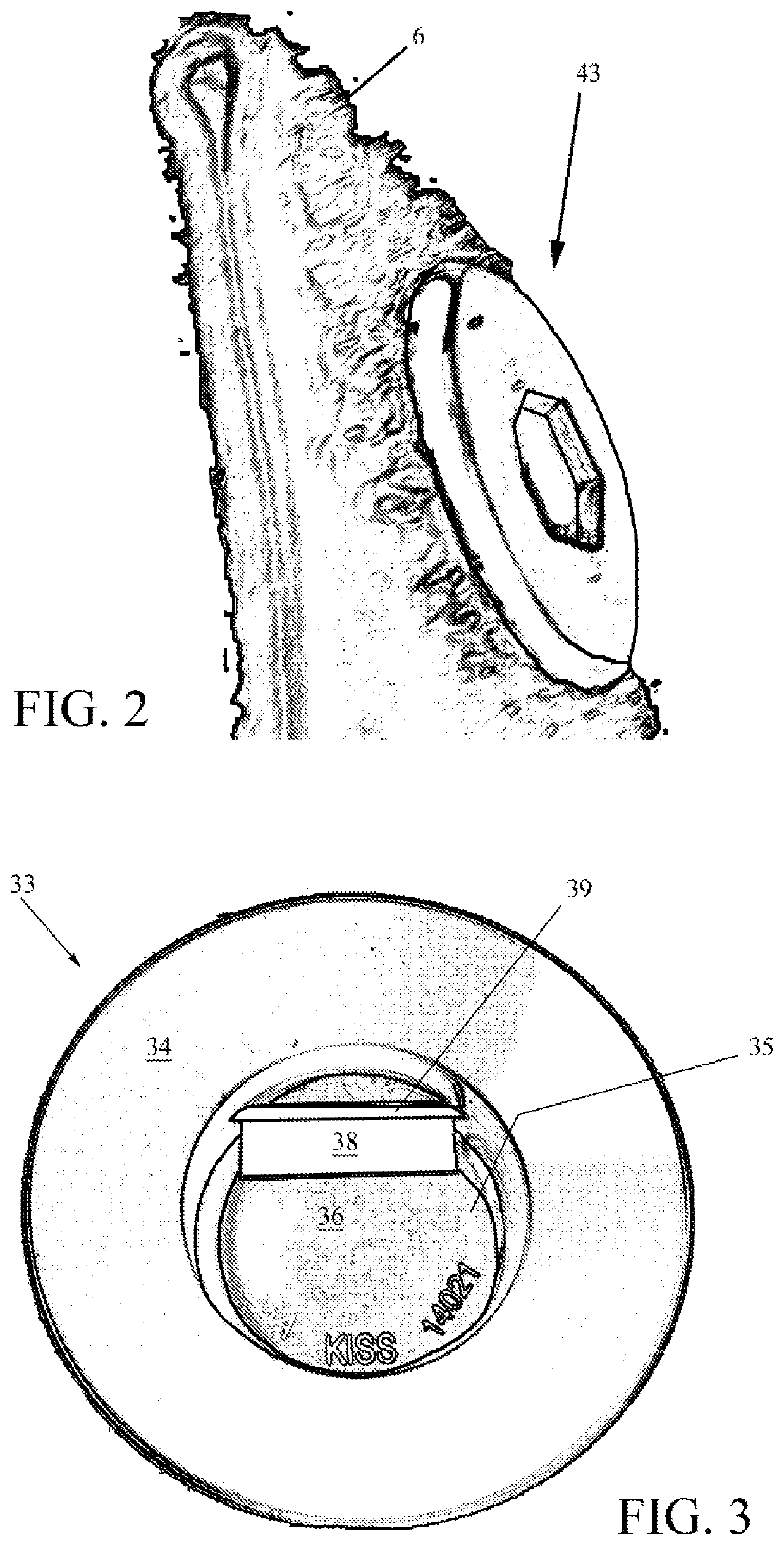
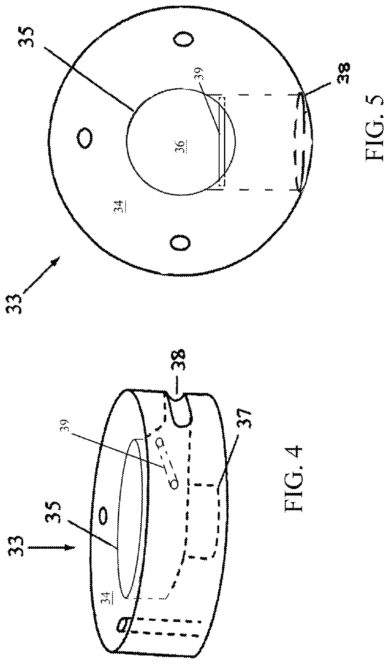
[0026]FIG. 1 is a perspective illustration of a sure-fit prosthetic anchoring system 2. The anchoring system 2 is adapted for a patient that has undergone a limb reduction surgery resulting in an above-the-knee amputation. In a preferred embodiment, the anchoring system 2 generally includes a commercially-available liner 10 equipped with upper and lower strap-anchors 4, 6, respectively. The upper strap anchor 4 is pivotally attached at one end by grommet-post 24 to a reinforcement plate 23, plate 23 being a plastic member that is sewn, bonded and / or attached with hook and loop peripherally onto the liner 10 at an upper outside position as shown. In a preferred embodiment the grommet-post 24 comprises two screw-together sections having 1′ flanges which sandwich the plate 23 and upper strap 4 together. The other end of upper strap 4 bears a buckle 14 with a short length of extension strap past the buckle 14 to provide a finger-grip. The extension strap past the buckle 14 may be a shor...


PUM


Abstract

A prosthetic suspension-mounting system which employs an improved flathead bolt and socket centering cup combination for securement of an amputee-limb enveloping liner within a prosthesis. The liner has a strap fixedly attached on the bottom end of the liner by a flathead bolt. The mounting system also includes a containment socket for seating the liner in the prosthesis using the head of the flathead bolt as a bearing surface against a floor of the socket. The containment socket has a slot there through at a position corresponding to the strap of the liner. The socket is provided with a disk-shaped recess having a flat floor, and the liner is provided with a distal flathead bolt having a flat head to provide a direct bearing surface against the floor of the socket. This provides a delimited bearing surface to keep the liner substantially centered within the prosthesis while still affording a lateral degree of freedom to avoid concentration of lateral forces.

Description

CROSS-REFERENCE TO RELATED APPLICATION(S)[0001]The present application is a division of U.S. patent application Ser. No. 14 / 809,907 filed 27 Jul. 2015, which in turn derives priority from U.S. Provisional Patent Application No. 62 / 030,831 filed Jul. 30, 2014, and is a continuation-in-part of U.S. Ser. No. 14 / 373,059 filed effective Dec. 14, 2012, both of which are incorporated herein by reference in their entireties.BACKGROUND OF THE INVENTION1. Field of the Invention[0002]The present invention relates to prosthetics and, more particularly, to a prosthetic suspension mounting assembly comprising an improved socket centering block or cup and liner bearing pin which combine to provide a more robust mounting solution for above-the-knee and below-the-knee amputation patients seeking a suspension-mount for their prosthetic limb.2. Description of the Background[0003]There are a variety of different types of prosthetic devices for patients that have had either transfemoral (above-knee) or ...

Claims


Application Information

Patent Timeline
Patent Type & Authority Patents(United States)
IPC IPC(8): A61F2/60A61F2/78A61F2/80
CPCA61F2/78A61F2/60A61F2/7812A61F2/80A61F2002/7831A61F2002/7875A61F2002/7881
Inventor MANTELMACHER, H. LEE
Owner KISS TECH LLC
Learn More