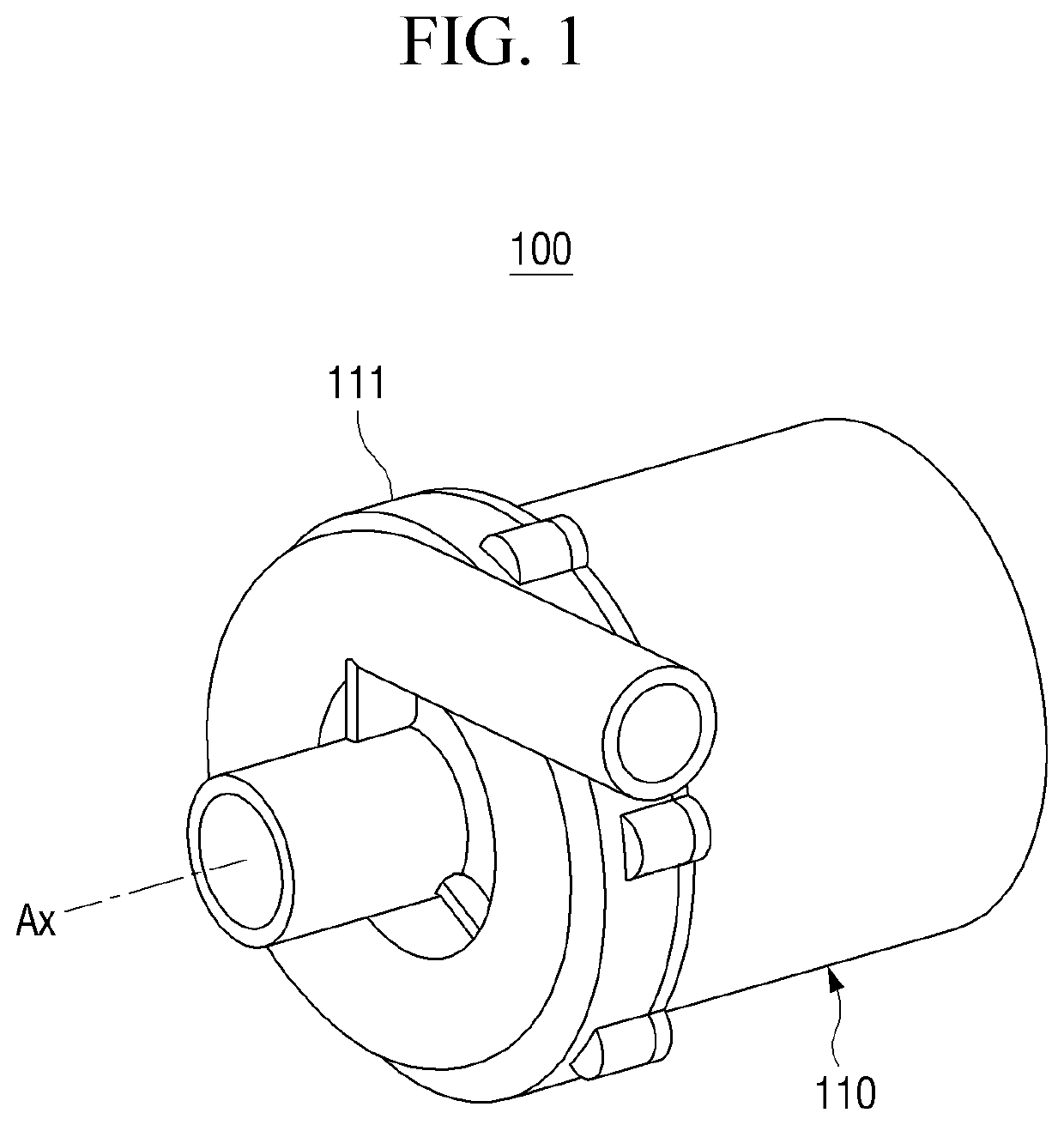
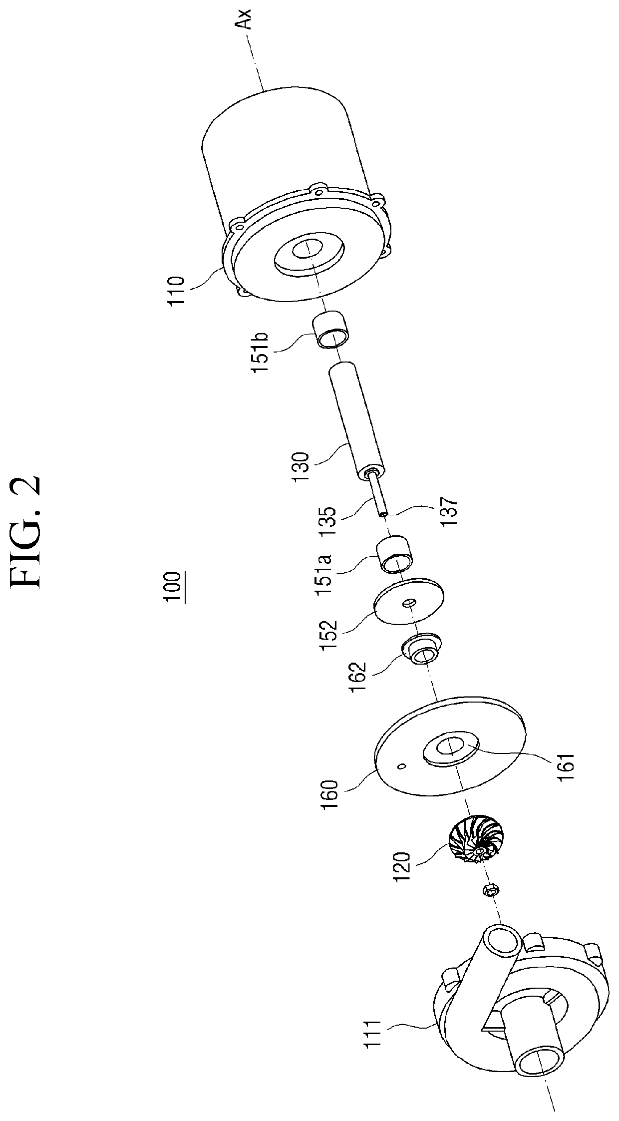
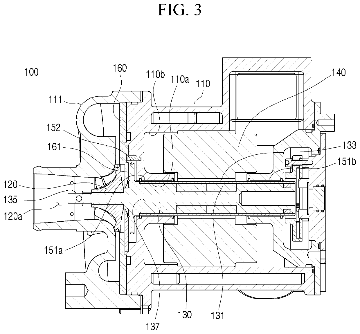
Rotary device

a rotary device and rotary technology, applied in the direction of machines/engines, mechanical equipment, machines/engines, etc., can solve the problems of reducing the efficiency adversely affecting increasing the size or so as to reduce the size and weight simplify the internal structure of the rotary device, and prevent flow loss

Active Publication Date: 2022-02-08
HANWHA POWER SYST CO LTD
View PDF7 Cites 0 Cited by
  • Summary
  • Abstract
  • Description
  • Claims
  • Application Information

AI Technical Summary

Benefits of technology

[0027]Accordingly, because no particular additional element for bringing in external air is needed, the internal structure of the rotary device can be simplified, and the size and the weight of the rotary device can be reduced.
[0028]In addition, because the rotary device includes a structure in which the internal air circulates along two cooling flow paths, flow loss can be prevented, and as a result, the efficiency of the rotary device can be improved.

Problems solved by technology

The provision of additional equipment may result in an increase in the size or the weight of the rotary device, adversely affecting the its size and weight of the rotary device.
Also, because the air used in cooling needs to be discharged out of the rotary device, the efficiency of the rotary device may decrease due to flow loss.
Therefore, a rotary device not only capable of preventing unnecessary flow loss through the efficient circulation of air along cooling flow paths while contributing to compactness and light weight of the rotary device is needed.

Method used


Image

  • Rotary device
  • Rotary device
  • Rotary device

Examples


Embodiment Construction

[0038]Advantages and features of the present disclosure and methods of accomplishing the same may be understood more readily by reference to the following detailed description of exemplary embodiments and the accompanying drawings. The present disclosure may, however, be embodied in many different forms and should not be construed as being limited to the embodiments set forth herein. Rather, these exemplary embodiments are provided so that this disclosure will be thorough and complete and will fully convey the concept of the present disclosure to those skilled in the art, and the present disclosure will only be defined within the scope of the appended claims. In the drawings, like reference numerals indicate like elements.

[0039]Unless otherwise defined, all terms (including technical and scientific terms) used herein have the same meaning as commonly understood by one of ordinary skill in the art to which the exemplary embodiments belong. It will be further understood that terms, su...


PUM


Abstract

A rotary device includes: a housing; an impeller disposed in the housing; a rotor disposed in the housing and configured to drive the impeller; and a labyrinth seal disposed between the impeller and the rotor in the housing and configured to control an amount of air injected through the impeller to cool the rotor. A flow path opening that penetrates through the rotor is formed inside the rotor along a rotational axis of the rotor and the labyrinth seal comprises a teeth portion having a predetermined number of steps provided in the labyrinth seal.

Description

CROSS-REFERENCE TO THE RELATED APPLICATION[0001]This non-provisional application claims priority from Korean Patent Application No. 10-2019-0045245 filed on Apr. 18, 2019 in the Korean Intellectual Property Office, the disclosure of which is incorporated herein by reference in its entirety.BACKGROUND1. Field[0002]Apparatuses consistent with exemplary embodiments relate to a rotary device, and more particularly, to a rotary device capable of cooling internal structures thereof during the driving of a rotor equipped with, for example, a permanent magnet.2. Description of the Related Art[0003]A rotary device is provided to meet the demand for the development of a high-performance, high-output electric device. Examples of the rotary device include an industrial compressor having a rotor-bearing structure, a pump, or a vehicular air supply device as well as a generator, an electric motor, or the like.[0004]In order to drive the rotary device, a rotating body having a permanent magnet emb...

Claims


Application Information

Patent Timeline
Patent Type & Authority Patents(United States)
IPC IPC(8): F04D25/08F04D25/06F04D29/10F04D17/10F04D29/08F16J15/447
CPCF04D25/082F04D17/10F04D25/0606F04D29/083F04D29/102F05B2240/57F05B2260/20F16J15/4476F04D29/057F04D29/5806F05D2240/61F16J15/447F04D29/584F04D29/053F04D29/284F05D2260/201F05D2210/12
Inventor HWANG, JIN SEOK
Owner HANWHA POWER SYST CO LTD
Why Eureka
Try Eureka