
Skin treatment device

a skin treatment and skin technology, applied in the field of skin treatment devices, can solve the problems of limited rejuvenation effect, inconvenient treatment, and insufficient skin lesions, and achieve the effects of fast healing of skin lesions, efficient and simple, and efficient and simpl

Active Publication Date: 2022-02-08
KONINKLJIJKE PHILIPS NV
View PDF15 Cites 1 Cited by
  • Summary
  • Abstract
  • Description
  • Claims
  • Application Information

AI Technical Summary

Benefits of technology

The invention is a skin treatment device that uses a simple and cost-effective fractional laser system to treat skin by combining collagen denaturation and fibroblast stimulation. This device can be easily modified from existing laser skin treatment devices or combined with various optical elements to implement the treatment. Overall, the invention provides a simple and effective method for skin treatment at a low cost.

Problems solved by technology

This is because laser beam profiles normally do not have very sharp edges, e.g. Gaussian beam profiles, and this results in intensity gradients in the tissue and thus thermal gradients.
Because of the limited size of the fibroblast stimulation zone, the rejuvenation effect is limited in the prior art teachings.
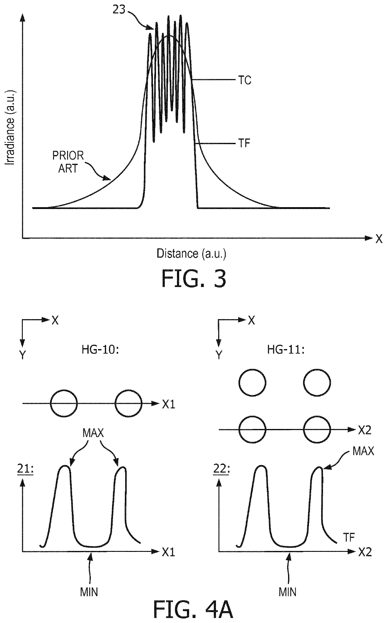
It is seen that a non-coherent treatment zone is obtained and the fibroblast stimulated areas are limited to relatively small areas surrounding these ‘hot spots’.
Therefore, when multiple single modes are closely spaced, the resulting beam profile will smear out and will not result in a non-uniform intensity distribution with ripples as shown in FIG. 3, as emitted by an array of multi-mode emitters or lasers.
In this case, a single emitter cannot provide the above mentioned result.
However, the relative amount of power that will be available in the higher-order modes will be significantly reduced as the order number becomes higher, thereby limiting the preferred options of m, n<4, alternatively 6 or 8.
Because of the significant differences in beam diameter, the aperture can cause significant diffraction losses for the higher-order modes without impacting the lower-order modes.

Method used


Image

  • Skin treatment device
  • Skin treatment device
  • Skin treatment device

Examples


Embodiment Construction

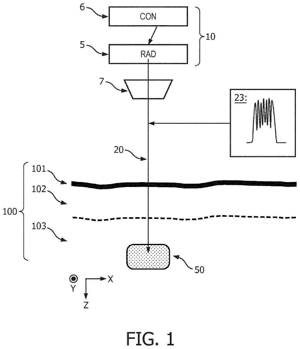
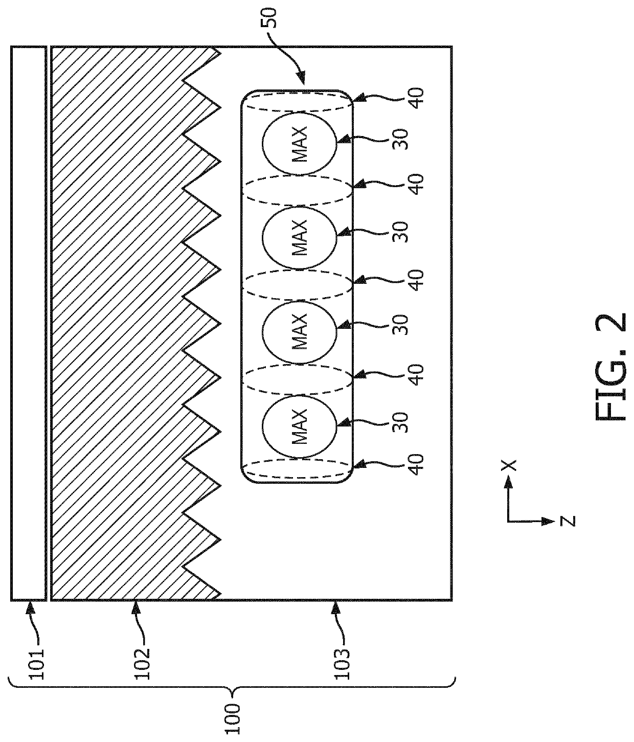
[0058]FIG. 1 shows a schematic cross-sectional drawing of a skin treatment device 10 according to an embodiment of the invention. The skin treatment device 10 is configured and arranged for fractional treatment of the skin 100 of a human being, although non-human skin may also be treated in some variants. The skin treatment device 10 may be a single entity for convenient use. The skin 100 of a human is normally considered to have three parts, the upper stratum corneum 101, the epidermis 102, and the dermis 103. In the shown embodiment, the laser beam 20 is directed, e.g. focused, to the dermis 103, where a treatment zone 50 is shown, but any part, or combination, of the skin 100 may be treated according to the present invention, see FIG. 6. More details about human skin interaction with laser can be found in Markolf H. Niemz, “Laser-Tissue interactions”, Springer publications (1996), which is hereby incorporated by reference in its entirety. For an overview of the effect of the temp...


PUM


Abstract

The invention relates to a skin treatment device (10) for fractional treatment of the skin (100) of a human being. A radiation source (5) emits a multi-mode laser beam (20) with a superposition (23) of mutually different higher-order laser modes. The multi-mode laser beam is configured by said superposition of different laser modes to simultaneously cause a first plurality of high-intensity zones, where the thermal threshold (TC) for collagen denaturation for the treatment zone (50) of the skin is at least reached, and a second plurality of low-intensity zones where the thermal threshold (TF) for fibroblast stimulation for the treatment zone of the skin is at least reached. This is advantageous for obtaining a skin treatment device with a simple and therefore low-cost fractional laser skin treatment system for combined collagen denaturation and fibroblast stimulation. The skin treatment device is based on non-uniform laser radiation in the form of the multi-mode laser beam.

Description

[0001]This application is the U.S. National Phase application under 35 U.S.C. § 371 of International Application No. PCT / EP2016 / 080300, filed on Dec. 8, 2016, which claims the benefit of International Application No. 15199648.5 filed on Dec. 11, 2015. These applications are hereby incorporated by reference herein.FIELD OF THE INVENTION[0002]The invention relates generally to the treatment of skin of a human being, using a skin treatment device. The invention particularly relates to a device for performing this treatment.BACKGROUND OF THE INVENTION[0003]Laser skin rejuvenation is an intervention that generates new skin tissue by intentionally damaging the skin by optical means. In selective non-ablative photothermolysis based on water absorption, tissue is heated between 60 and 100° C. to create damaged thermal zones to induce new collagen growth, without ablation or vaporization of the skin.[0004]In some home use devices, so-called fractional rejuvenation is often performed through ...

Claims


Application Information

Patent Timeline
IPC IPC(8): A61B18/20A61N5/06A61N5/067A61B18/22A61B18/00
CPCA61B18/203A61N5/0616A61B2018/0047A61B2018/2035A61B2018/2266A61N2005/067A61N5/067
Inventor VARGHESE, BABUBARAGONA, MARCOPALERO, JONATHAN ALAMBRAJURNA, MARTINHORTON, MARGARET RUTHEZERSKAIA, ANNA
Owner KONINKLJIJKE PHILIPS NV
Learn More