
Apparatus, method and system for autonomous driving

a technology of autonomous driving and autonomous driving, applied in the direction of vehicle position/course/altitude control, process and machine control, instruments, etc., can solve the problems of reducing the accuracy of the autonomous driving path obtained through communication, and the accuracy of the autonomous driving path is reduced. , to achieve the effect of improving reducing the accuracy of the autonomous driving control, and reducing the accuracy of the autonomous driving path

Active Publication Date: 2021-12-14
HYUNDAI MOBIS CO LTD
View PDF27 Cites 0 Cited by
  • Summary
  • Abstract
  • Description
  • Claims
  • Application Information

AI Technical Summary

Benefits of technology

The invention improves the accuracy and precision of autonomous driving control by using sensor data from a vehicle-mounted sensor and communication information that is up-to-date. This enhances the performance of autonomous driving control.

Problems solved by technology

However, the autonomous driving based on the vehicle-mounted sensor has a limitation in that the preciseness decreases due to a systematic limit of the sensor, and accuracy of the autonomous driving path obtained through communication decreases due to non-up-to-date (non-up-to-date of map data, etc.) of communication information.

Method used


Image

  • Apparatus, method and system for autonomous driving
  • Apparatus, method and system for autonomous driving
  • Apparatus, method and system for autonomous driving

Examples


embodiment 1

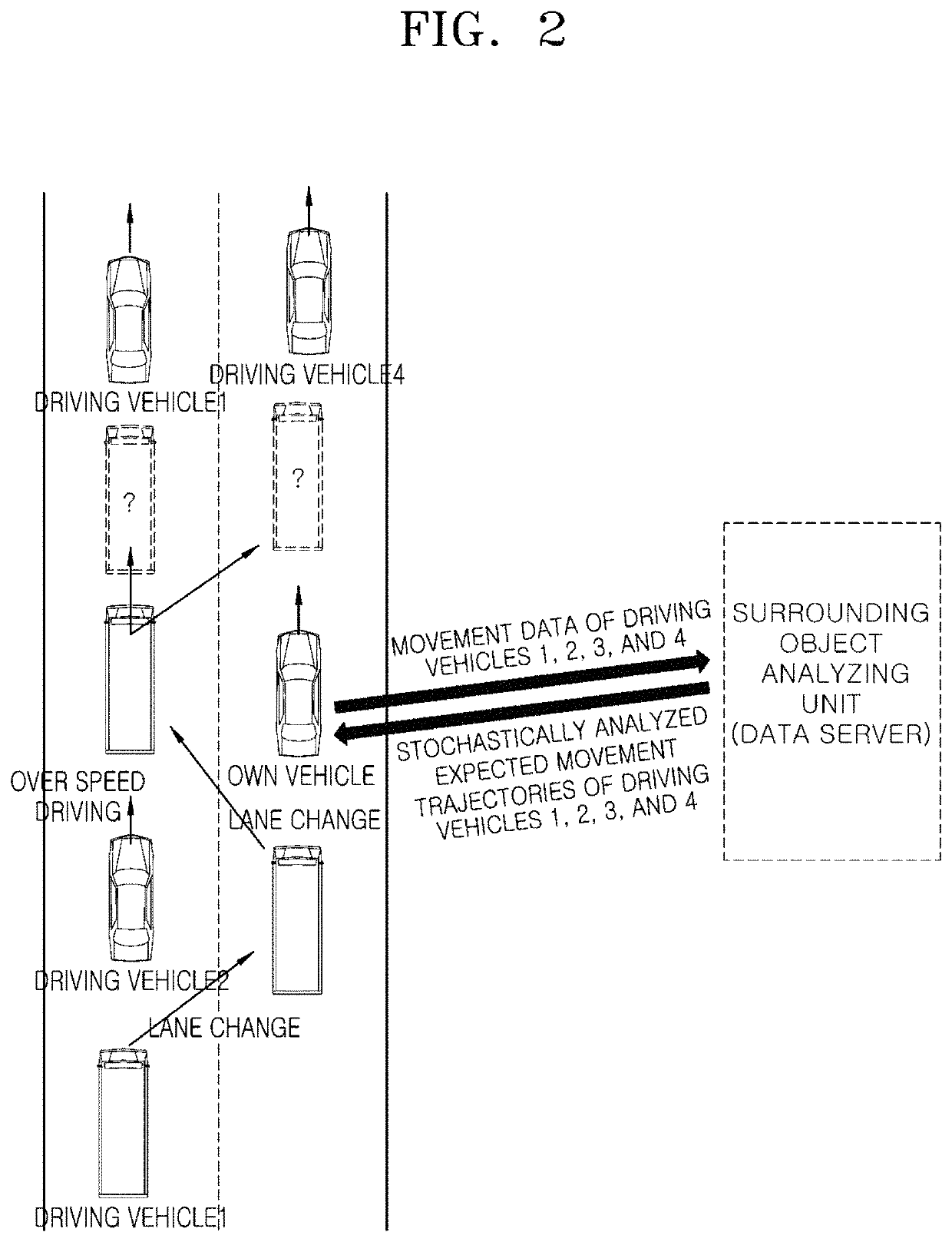
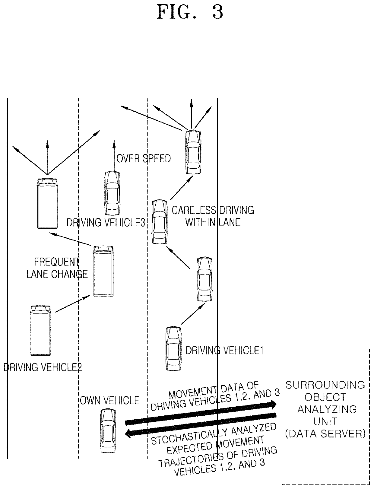
[0040]FIG. 1 is a block configuration diagram for describing an autonomous driving control device according to a first embodiment of the invention, and FIGS. 2 and 3 are exemplary drawings for describing a process in which a control unit in the autonomous driving control device generates an autonomous driving path according to the first embodiment of the invention.

[0041]In relation to FIG. 1, the autonomous driving control device according to a first embodiment of the invention may include an interface unit 10, a positioning unit 20, a map data storage unit 30, a sensor unit 40, a control unit 50, a surrounding object analyzing unit 60, and a autonomous driving unit 70.

[0042]The interface unit 10 performs an input / output function for receiving a manipulation of a user and outputting driving information of an own vehicle, etc., and may include all components capable of performing an input / output function, such as a voice recognition device and 3D hologram as well as a head up display...

embodiment 2

[0066]FIG. 6 is a block configuration diagram for describing an autonomous driving control device according to a second embodiment of the invention, and FIGS. 7 and 8 are exemplary drawings for describing a process in which a sensor unit senses a surrounding object and a surrounding environment in the autonomous driving control device according to the second embodiment of the invention. FIGS. 9 and 10 are exemplary drawings for describing a process in which a data analyzing unit analyzes movement data of the surrounding object in the autonomous driving control device according to the second embodiment of the invention, and FIGS. 11 and 12 are exemplary drawings for describing a process in which a collision with the surrounding object is avoided through accident data analyzed by the data analyzing unit in the autonomous driving control device according to the second embodiment of the invention.

[0067]In relation to FIG. 6, the autonomous driving control device according to the second ...


PUM


Abstract

An autonomous driving device may include: a sensor configured to sense a surrounding object of an own vehicle, a controller configured to generate an autonomous driving path of the own vehicle based on movement data of the surrounding object sensed by the sensor unit, and a surrounding object analyzer configured to receive the movement data of the surrounding object from the controller and stochastically analyze an expected movement trajectory of the surrounding object. The controller may generate the autonomous driving path based on the expected movement trajectory of the surrounding object that is stochastically analyzed by the surrounding object analyzing unit.

Description

CROSS-REFERENCES TO RELATED APPLICATIONS[0001]This application claims priority from and the benefit of Korean Patent Applications No. 10-2017-0118395 and 10-2017-0168690, filed on Sep. 15, 2017 and Dec. 8, 2017, respectively, which are hereby incorporated by reference for all purposes as if set forth herein.BACKGROUNDField[0002]Exemplary embodiments of the invention relate to an apparatus, method and system for autonomous driving, and more particularly, to an apparatus, method and system for autonomous driving which perform autonomous driving along an autonomous driving path generated to avoid a collision with a surrounding object.Discussion of the Background[0003]Today's automotive industry is proceeding toward a direction of realizing autonomous driving through which driver's intervention in driving is minimized. An autonomous driving vehicle indicates a vehicle that recognizes surrounding environments through a sensing and processing function, autonomously determines a path, and ...

Claims


Application Information

Patent Timeline
Patent Type & Authority Patents(United States)
IPC IPC(8): B60W30/095G08G1/16B60W30/09G05D1/00G05D1/02G08G1/01
CPCB60W30/0956B60W30/09B60W30/0953G05D1/0088G05D1/0212G05D1/0238G08G1/0112G08G1/166G05D2201/0213G05D1/021G05D1/0278G08G1/164G08G1/0133G08G1/0145B60W30/10B60W30/16B60W60/00274B60W2554/408B60W2556/05B60W2554/4042B60W2554/4046
Inventor LEE, JOO YEOB
Owner HYUNDAI MOBIS CO LTD
Learn More