Driver system
a technology of drive shafts and driveshafts, applied in the direction of pulse technique, electroluminescent light sources, electric lighting sources, etc., can solve the problems of complex and costly overall circuit design
- Summary
- Abstract
- Description
- Claims
- Application Information
AI Technical Summary
Benefits of technology
Problems solved by technology
Method used
Image
Examples
first embodiment
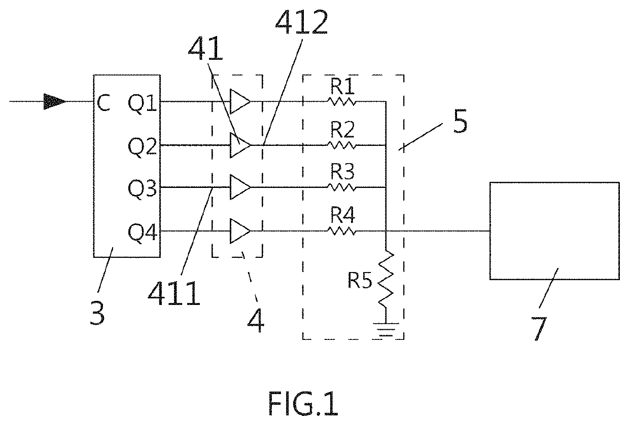
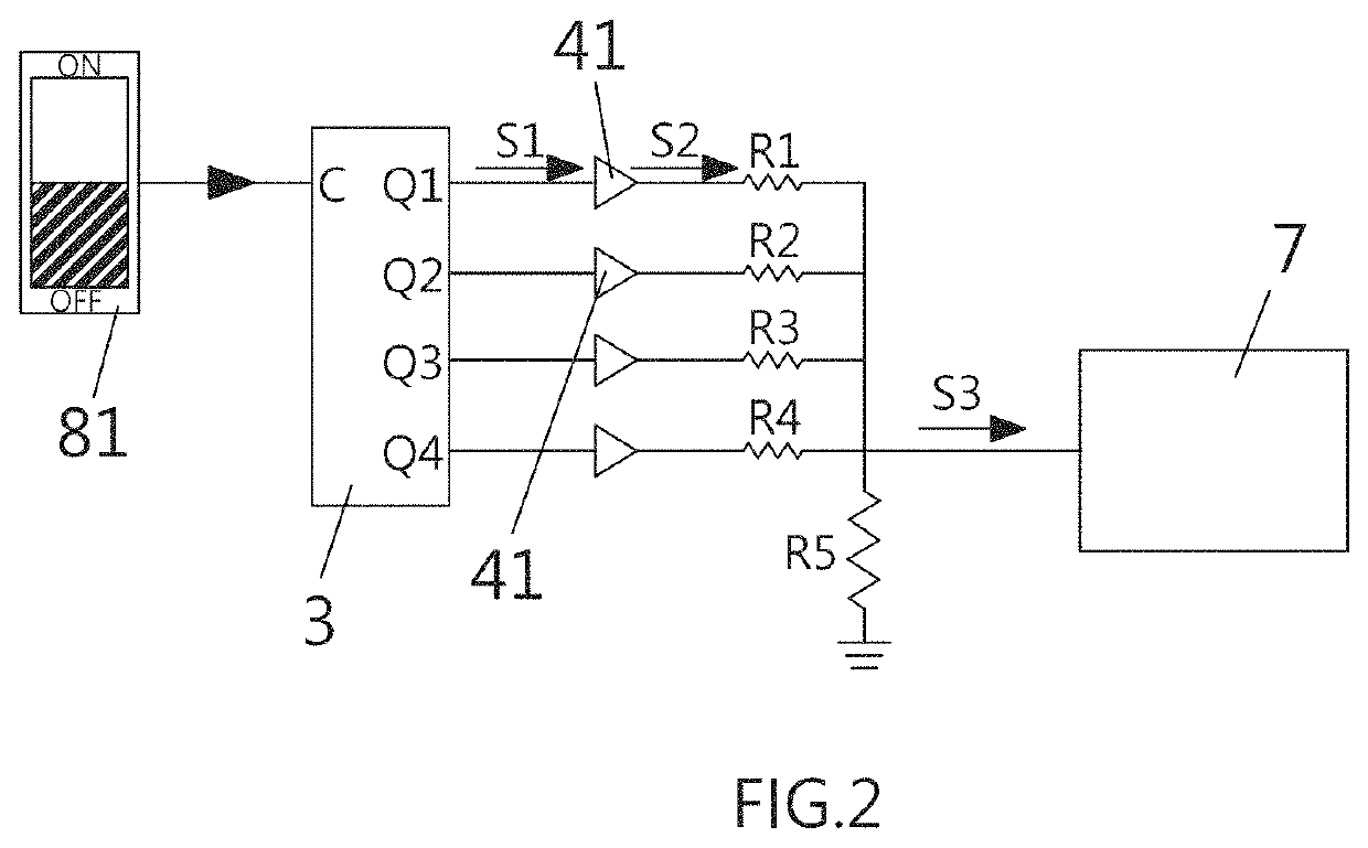
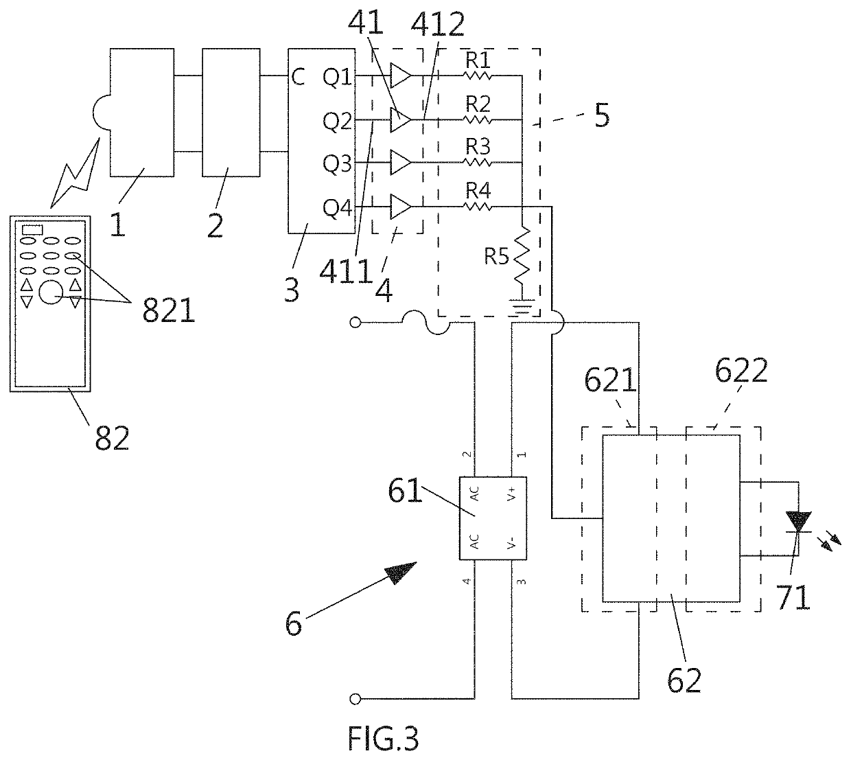
[0027]FIG. 1 is a schematic diagram showing the circuit of the driver system according to the invention. The driver system disclosed herein comprises a counter unit 3, a buffer unit 4, and a voltage regulation unit 5.
[0028]The counter unit 3 includes a first input terminal C adapted to receive a driving signal and a plurality of first output terminals Q1, Q2, Q3, and Q4. Responsive to receiving the driving signal, the counter unit 3 sequentially activates the first output terminals Q1, Q2, Q3, and Q4, one at a time, following a predetermined counting sequence, thereby outputting a control signal. The counter unit 3 may comprise a Johnson counter and is adapted to sequentially output control signals from the output terminals Q1, Q2, Q3, and Q4 according to the received driving signal. It is known in the art that the number of first output terminals is not limited to that described herein, and additional counter unit(s) may be included in the device. A plurality of counter units can b...
third embodiment
[0039]FIG. 4 is a schematic diagram showing the circuit of the driver unit according to the invention. The driver unit comprises a rectifier circuit 61, a voltage stabilization circuit 63 and a constant current circuit 64. The voltage stabilization circuit 63 includes a resistor R6, a Zener diode Z connected in series with the resistor R6, and a first operational amplifier 633. The serially connected resistor R6 and Zener diode Z are electrically connected to the rectifier circuit 61 to receive the DC power source, thereby generating a constant voltage based on the DC power source. The first operational amplifier 633 is adapted to output a predetermined voltage upon receiving the constant voltage and the control voltage. The constant current circuit 64 includes a transistor Q and a resistor R7 connected in series. The constant current circuit 64 is connected in series with the light-emitting diodes mounted in the light source module 71. The transistor Q is adapted to drive the light...
fifth embodiment
[0042]FIG. 6 is a schematic diagram showing the driver system according to the invention. The driver system comprises a counter unit 3, a voltage regulation unit 5 and an operational amplifier unit 9, which differs from the embodiments above in the provision of the operational amplifier unit 9, in place of the buffer unit according to the embodiments above, for connection to the voltage regulation unit 5. The voltage regulation unit 5 is similarly provided with resistors R1˜R4 connected to the first output terminals Q1, Q2, Q3, Q4, respectively. The control signal output from the activated first output terminal Q1, Q2, Q3, Q4 of the counter unit is transmitted through one of the resistors in the voltage regulation unit 5 to reach the operational amplifier unit 9, which conducts computation based on the control signal and then outputs a specific control voltage. The control voltage output is isolated due to the provision of the operational amplifier unit 9. The operational amplifier ...
PUM
 Abstract
Description
Claims
Application Information
 - R&D
- Intellectual Property
- Life Sciences
- Materials
- Tech Scout
- Unparalleled Data Quality
- Higher Quality Content
- 60% Fewer Hallucinations
Browse by: Latest US Patents, China's latest patents, Technical Efficacy Thesaurus, Application Domain, Technology Topic, Popular Technical Reports.
© 2025 PatSnap. All rights reserved.Legal|Privacy policy|Modern Slavery Act Transparency Statement|Sitemap|About US| Contact US: help@patsnap.com


