Heat exchange structure of telecommunication cabinet

a technology for telecommunication cabinets and heating elements, which is applied in the direction of electrical apparatus construction details, cabinet/cabinet/drawer, instruments, etc., can solve the problems of high power consumption of 5g base stations, inability to effectively dissipate heat generated by heating elements within the cabinet, and inability to meet the needs of users, so as to improve heat exchange efficiency and heat dissipation effect, improve dustproofing and waterproofing, and increase air resistance

Active Publication Date: 2021-11-16
SUPER MICRO COMP
View PDF8 Cites 5 Cited by
  • Summary
  • Abstract
  • Description
  • Claims
  • Application Information

AI Technical Summary

Benefits of technology

The disclosed heat exchange structure for a telecommunication cabinet improves space utilization, reduces air resistance, and enhances heat dissipation efficiency. It utilizes separate flow paths for hot and external air to prevent dust and water infiltration. The hot and external air flow through linear pipes without turns or bends, resulting in improved heat exchange efficiency and dissipation. By optimizing the use of internal space, the telecommunication cabinet can be mounted at higher elevations, saving ground space and minimizing interference with millimeter waves.

Problems solved by technology

The millimeter wave used by 5G technology is susceptible to interference and interruption, so a larger number of small cells must be deployed to achieve requisite coverage.
Furthermore, 5G base stations have high power consumption than their 4G counterparts, so the heat generated by the heating elements within the cabinet needs to be effectively dissipated to maintain normal operations.
The existing design of heat exchangers used in 5G telecommunication cabinets utilizes multiple internal fans, which occupy a large volume of internal space and increase the difficulty of optimizing the use of the internal space of the cabinet.
Additionally, the aforementioned heat exchanger is often designed with wind turning that is likely to generate airflow resistance and cause heat accumulation.

Method used


Image

  • Heat exchange structure of telecommunication cabinet
  • Heat exchange structure of telecommunication cabinet
  • Heat exchange structure of telecommunication cabinet

Examples


Embodiment Construction

[0016]In the present disclosure, numerous specific details are provided, such as examples of apparatus, components, and methods, to provide a thorough understanding of embodiments of the invention. Persons of ordinary skill in the art will recognize, however, that the invention can be practiced without one or more of the specific details. In other instances, well-known details are not shown or described to avoid obscuring aspects of the invention.

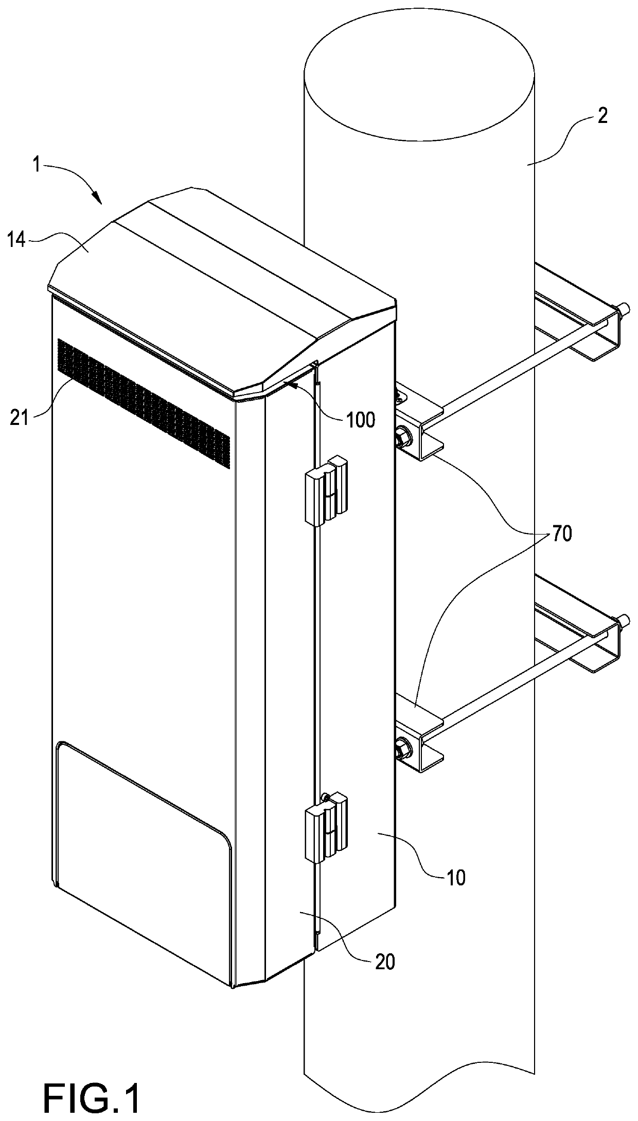
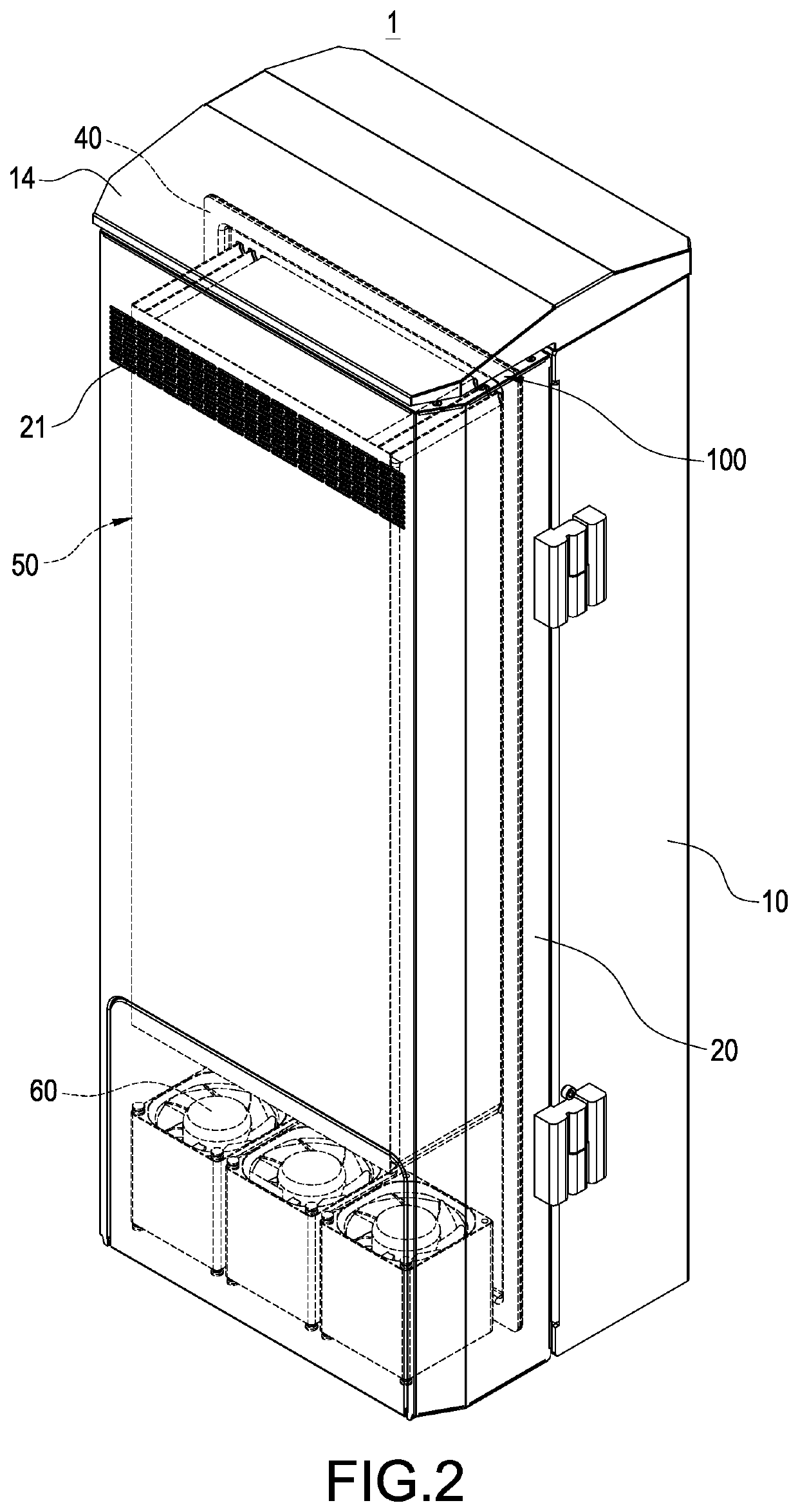
[0017]Please refer to FIG. 1 to FIG. 3, which depict a schematic view of the telecommunication cabinet in an operation status of this disclosure, a perspective schematic view of the telecommunication cabinet of this disclosure and a perspective schematic view of the second cabinet body being opened of this disclosure. The heat exchange structure of the telecommunication cabinet 1 of this disclosure includes a first cabinet body 10, a second cabinet body 20, at least one internal fan 30, a partition board 40, a plurality of heat dissipation ...


PUM


Abstract

A telecommunication cabinet includes a first and a second cabinet bodies, an internal fan, a partition board, multiple heat dissipation pipes and an external fan. The first cabinet body includes an upper slot and a lower slot. The second cabinet body covers the first cabinet body and includes an air inlet and an air outlet. The internal fan is arranged in the first cabinet body. The partition board is connected with the second cabinet body and includes multiple air vents and multiple air intakes. The heat dissipation pipes are disposed in the second cabinet body and include multiple upper nozzles and multiple lower nozzles. Multiple heat dissipation channels are disposed between the heat dissipation pipes. The external fan is disposed on a bottom inside the second cabinet body.

Description

BACKGROUND OF THE INVENTIONTechnical Field[0001]The technical field relates to a telecommunication cabinet, and more particularly relates to a heat exchange structure of a telecommunication cabinet.Description of Related Art[0002]The millimeter wave used by 5G technology is susceptible to interference and interruption, so a larger number of small cells must be deployed to achieve requisite coverage. In addition, small cells are usually deployed in densely populated metropolitan areas where demand is greatest. In order to reduce the amount of space occupied and avoid interference or interruption, current plans for 5G base stations call for installation in high places such as telecommunication poles, signal poles, street lamp poles, or elevated bridges.[0003]Since small cells are usually deployed outdoors, preventing the intrusion of moisture or dust into the small cells is a significant concern. Furthermore, 5G base stations have high power consumption than their 4G counterparts, so ...

Claims


Application Information

Patent Timeline
Patent Type & Authority Patents(United States)
IPC IPC(8): G06F1/16H05K5/00H05K7/00H05K7/20H05K7/18
CPCH05K7/20572H05K7/186H05K7/206H05K5/0204
Inventor CHEN, CHIA-WEICHAO, TIENEN
Owner SUPER MICRO COMP
Why Eureka
Try Eureka