
Brain cooling method and portable device

a brain cooling and portable technology, applied in the field of brain cooling methods and portable devices, can solve the problems of brain damage, brain damage, and brain damage, and achieve the effects of mild brain cooling, reduced perfusion to the brain, and mild brain damag

Active Publication Date: 2021-11-16
ZHU MICHELLE YUE
View PDF6 Cites 1 Cited by
  • Summary
  • Abstract
  • Description
  • Claims
  • Application Information

AI Technical Summary

Benefits of technology

This patent describes a device and method for cooling the brain through the nasal cavity to treat various brain-related issues such as traumatic brain injury, strokes, and migraines. The device is small, energy-efficient, and easy to operate. It uses a control system to autonomously control the temperature of the brain. The device includes a cooling device with solid-state thermoelectric Peltier cooler devices that can induce mild brain cooling. The control system receives user-defined target temperature ranges and adjusts the cooling device and fan speed accordingly to maintain the brain temperature within the set range. The device is portable and easy to transport.

Problems solved by technology

Cerebral ischemia is the lack of oxygen to the brain, often resulting in disabilities ranging from transient neurological damage to permanent brain damage.
However, in hospitals, severe brain damage from lack of oxygen after cardiac arrest remains prominent.
Annually, over one million people in the United States suffer from traumatic brain injury, which may also result in brain damage.
Current noninvasive nasopharyngeal cerebral cooling devices require large amounts of consumable supplies to operate, which result in bulky equipment and high chemical refill costs.
Additionally, current intranasal cooling devices use a plurality of chemical fluids to be sprayed into the nasal cavity, wherein evaporation of the liquid results in evaporative heat loss that cools the nasal cavity.
Although coolant has shown to be safe for use on humans, when it is sprayed into nasal cavities in large quantities, and possibly breathed into the lungs, it may lead to deleterious side effects.
As coolant evaporates, some coolant travels to and is partially acted on the nose and wasted, often resulting in frozen white noses.
Although this method does not require consumable or potentially harmful chemical resources, it has multiple limitations.
Cold fluid cannot easily penetrate the protective layers between the helmet and the skull.
However, chilled air may not be available for personnel to administer to the patient outside of clinical settings.

Method used


Image

  • Brain cooling method and portable device
  • Brain cooling method and portable device
  • Brain cooling method and portable device

Examples


Embodiment Construction

[0036]The detailed embodiments of the present invention are disclosed herein. The invention is not limited to the disclosed description, which is merely exemplary of the embodiments of the invention. The invention can be embodied in different forms without departure from the principle introduced here.

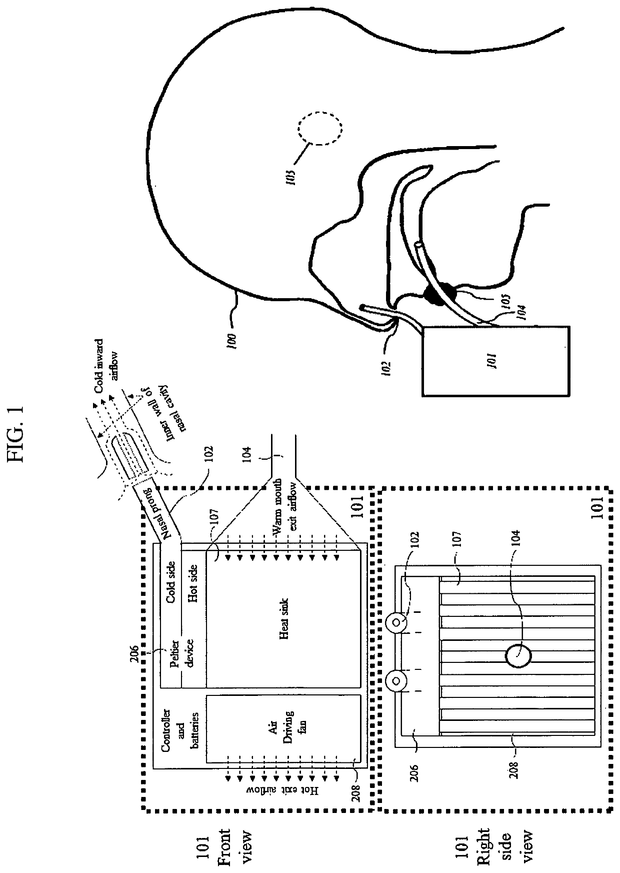
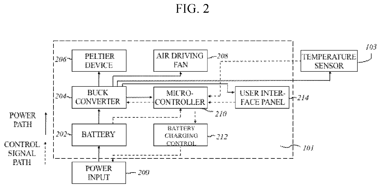
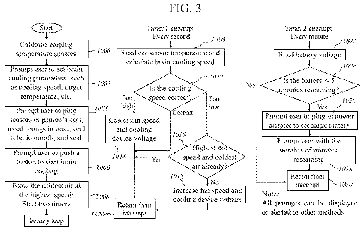
[0037]In accordance with the present invention, and with reference to FIG. 1-3, a cooling device for noninvasive nasopharyngeal cerebral cooling is disclosed. One form of the invention is illustrated and is indicated in general by numeral 101. The device 101 has a cooling source composed of solid-state coolers 206, and a temperature-sensing accessory 103. These elements are coupled with nasal prongs 102, and oral tube 104 for circulation of air through the nasal and oral cavities, particularly, the upper nasal cavity. A control sub-system controls the cooling elements and monitors cerebral temperatures. As such, the microcontroller 210 receives input data from the temperature sensor 103...


PUM


Abstract

A noninvasive, brain cooling method and device for cerebral cooling via a patient's nasopharyngeal cavity, is described. Thermal conductive nasal prongs are inserted into a nasal cavity and are cooled by thermoelectric cooling elements. An outward air driving fan inside the device drives a cold air current through the nasal and oral cavities. Heat transfer between the cold air and the surface of the nasal cavity cools the nasal cavity, which in turn, cools a patient's brain. Real-time temperature sensing data provides feedback for closed-loop cooling control.

Description

REFERENCE CITEDU.S. Patent Document Cited[0001]9,849,025Dec. 6, 2017Zaveri9,775,741Oct. 3, 2017Barbut9,757,272Sep. 12, 2017Belson9,744,071Aug. 29, 2017Harikrishna9,737,434Aug. 22, 0217Allison9,737,103Aug. 22, 2017Preston-Powers9,717,623Aug. 1, 2017Hyogo9,629,745Apr. 25, 2017Harikrishna9,622,909Apr. 18, 2017Kulstad9,522,244Dec. 20, 2016Takeda9,445,940Sep. 20, 2016Yon9,414,959Aug. 16, 2016Belson9,375,345Jun. 28, 2016Levinson9,358,150Jun. 7, 2016Rozenberg9,320,644Apr. 26, 2016Kreck9,278,023Mar. 8, 2016Dabrowiak8,721,699May 13, 2014Barbut8,512,280Aug. 20, 2013Rozenberg8,480,723Jul. 9, 2013Barbut8,454,671Jun. 4, 2013Lennox8,313,520Nov. 20, 2012Barbut8,308,786Nov. 13, 2012Rozenberg8,303,637Nov. 6, 2012Mori8,157,767Apr. 17, 2012Rozenberg7,879,077Feb. 1, 2011MacHold7,231,771Jun. 19, 2007McMurry7,189,253Mar. 13, 2007Lunderqvist7,052,509May 30, 2006Lennox20140053834A1 Feb. 27, 2014Harikrishna20140343641A1 Nov. 20, 2014Barbut20150119962A1 Apr. 30, 2015Kulstad20180064574A1 Mar. 8, 2018AdairFore...

Claims


Application Information

Patent Timeline
Patent Type & Authority Patents(United States)
IPC IPC(8): A61F7/12A61M16/04A61F7/00
CPCA61F7/12A61M16/0461A61F2007/0002A61F2007/0056A61F2007/0064A61M2205/3606A61F2007/0059A61F2007/0063A61F2007/0076A61F2007/0096A61M13/003A61M16/0066A61M16/0666A61M2205/362A61M2205/3673A61M2205/502A61M2205/8206A61M2210/0618A61M2210/0662A61M2210/0693A61M2230/50A61M16/049A61M2230/005
Inventor ZHU, MICHELLE YUE
Owner ZHU MICHELLE YUE
Learn More