
Exhaust gas purifying catalyst

a purifying catalyst and exhaust gas technology, applied in physical/chemical process catalysts, metal/metal-oxide/metal-hydroxide catalysts, separation processes, etc., can solve the problems of catalytic performance and nox purification performance decreasing, and achieve excellent catalytic activity, high hydrothermal durability, and improved hydrothermal durability

Active Publication Date: 2021-11-09
CATALER CORP
View PDF25 Cites 0 Cited by
  • Summary
  • Abstract
  • Description
  • Claims
  • Application Information

AI Technical Summary

Benefits of technology

[0009]With these circumstances in mind, the primary objective of the present invention is to provide an exhaust gas purifying catalyst having excellent hydrothermal durability.
[0020]In addition, the present invention provides an exhaust gas purifying apparatus provided with the exhaust gas purifying catalyst and a reducing agent supply mechanism which supplies a reducing agent for generation of ammonia to the exhaust gas at a position upstream in the exhaust pathway as compared to a position of the exhaust gas purifying catalyst. An exhaust gas purifying apparatus that exhibits higher hydrothermal durability and better NOx purifying performance than in the past is realized by this configuration.

Problems solved by technology

This leads to the problem of catalyst performance (for example, NOx purifying performance) decreasing.

Method used


Image

  • Exhaust gas purifying catalyst
  • Exhaust gas purifying catalyst
  • Exhaust gas purifying catalyst

Examples


example 1

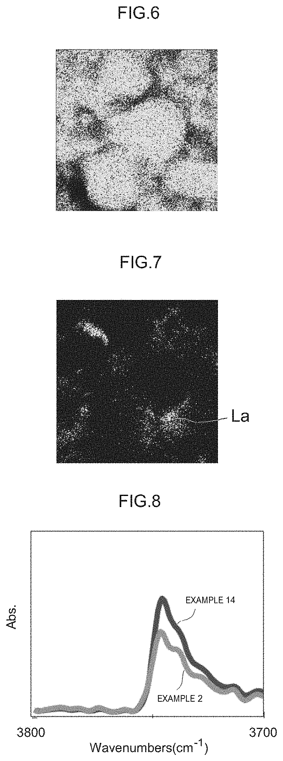
[0077]217 g of a Cu ion exchange zeolite (CHA, SiO2 / Al2O3 molar ratio=10) was mixed with a solution obtained by mixing 251 g of pure water, 21 g of a SiO2 sol and 31 g of a La2O3 sol, and stirred for 15 minutes. A slurry of La2O3-adhered zeolite particles was prepared in this way. The La2O3 sol was added at a quantity whereby the molar ratio of La contained in the La2O3 relative to Si contained in the zeolite (La2O3 / SiO2) was 0.00113 in terms of oxides. In addition, the amount of water in the slurry was adjusted so as to attain a slurry viscosity such that the slurry could be coated on a cordierite honeycomb substrate. The obtained slurry was coated on a cordierite honeycomb substrate at a quantity whereby the coating amount of the Cu ion exchange zeolite (the mass per 1 L of substrate volume) was 180 g / L after firing. Next, excess slurry was removed, and the substrate was then dried at 100° C. and heat treated (fired) for 1 hour at 500° C. A catalyst layer was formed on the surface...

example 2

[0078]An exhaust gas purifying catalyst was prepared using the same procedure as that used in Example 1, except that the amount of pure water was changed to 191 g, the amount of the SiO2 sol was changed to 49 g, the amount of the La2O3 sol was changed to 73 g, and the amount of the Cu ion exchange zeolite (CHA, SiO2 / Al2O3 molar ratio=10) was changed to 208 g.

example 3

[0079]An exhaust gas purifying catalyst was prepared using the same procedure as that used in Example 1, except that the amount of pure water was changed to 85 g, the amount of the SiO2 sol was changed to 97 g, the amount of the La2O3 sol was changed to 146 g, and the amount of the Cu ion exchange zeolite (CHA, SiO2 / Al2O3 molar ratio=10) was changed to 192 g.


PUM

PropertyMeasurementUnit
molar ratioaaaaaaaaaa
particle diameter D2aaaaaaaaaa
molar ratioaaaaaaaaaa

Abstract

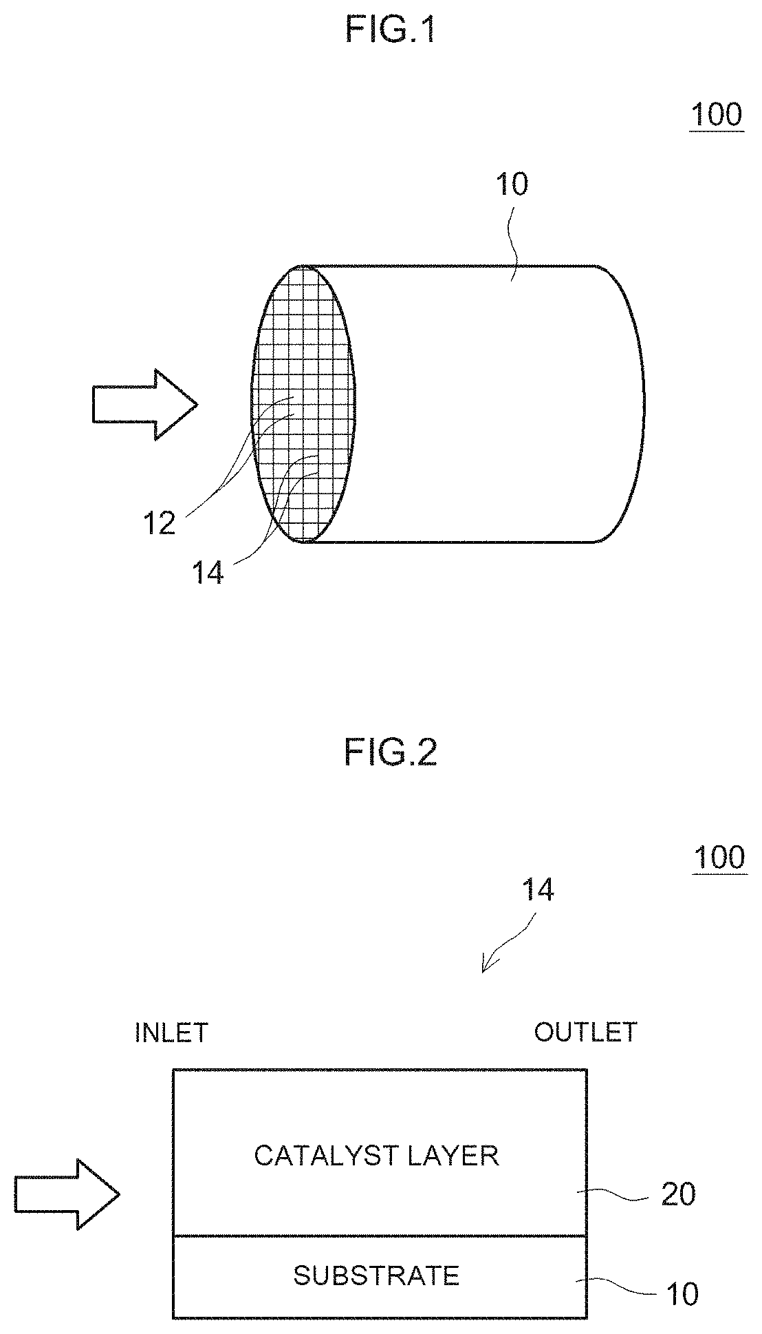
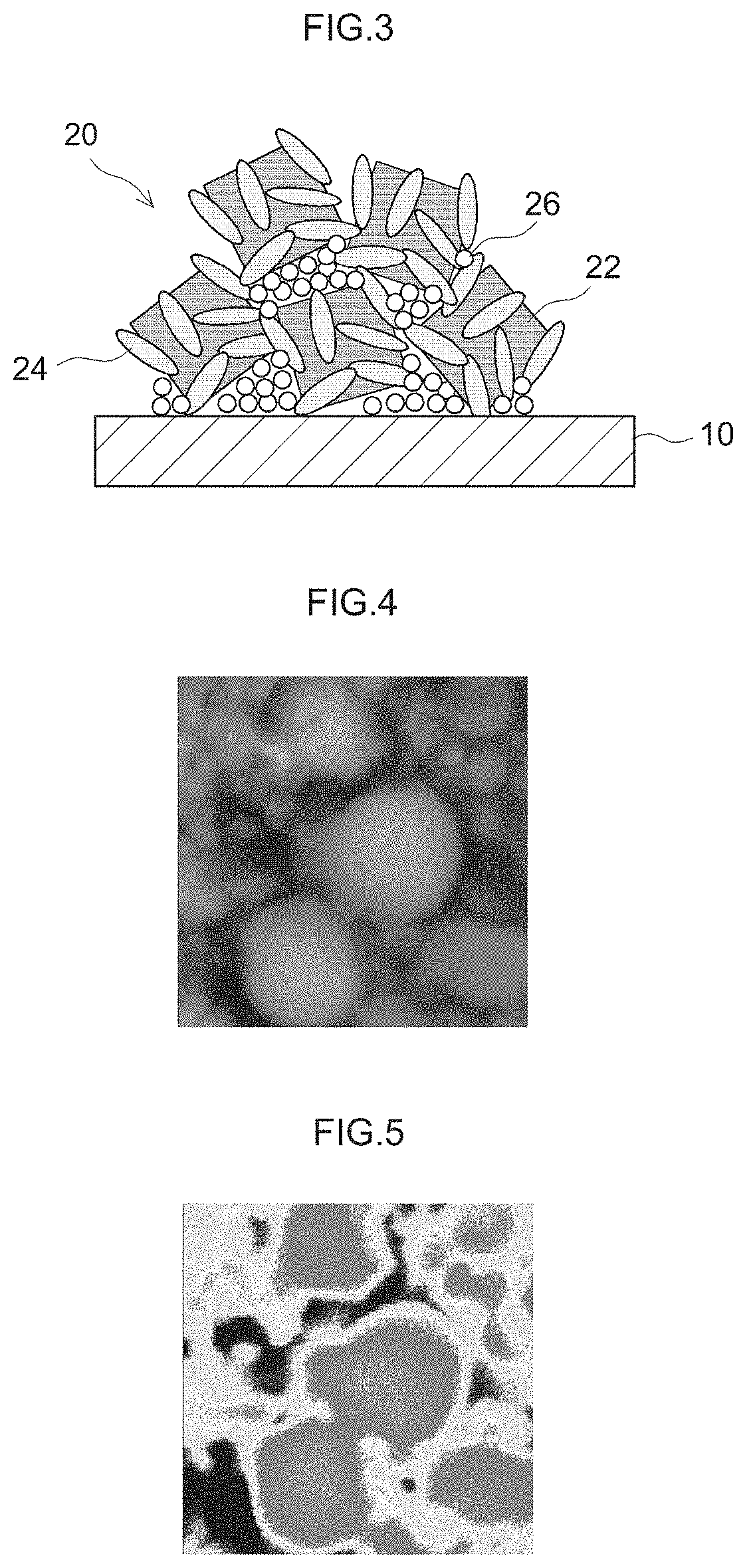
This exhaust gas purifying catalyst is provided with a substrate 10 and a catalyst layer 20 formed on a surface of the substrate 10. The catalyst layer 20 contains zeolite particles 22 that support a metal, and a rare earth element-containing compound 24 that contains a rare earth element. The rare earth element-containing compound 24 is added in such an amount that the molar ratio of the rare earth element relative to Si contained in the zeolite 22 is 0.001 to 0.014 in terms of oxides.

Description

CROSS REFERENCE TO RELATED APPLICATIONS[0001]This application is a National Stage of International Application No. PCT / JP2018 / 005691 filed on Feb. 19, 2018, which claims priority to Japanese Application No. 2017-029297 filed on Feb. 20, 2017 and Japanese Application No. 2017-224344 filed on Nov. 22, 2017, the contents of which are hereby incorporated by reference in their entirety.TECHNICAL FIELD[0002]The present invention relates to an exhaust gas purifying catalyst. More specifically, the present invention relates to an exhaust gas purifying catalyst that cleans exhaust gases emitted from an internal combustion engine such as a motor vehicle engine.[0003]Moreover, the present application claims priority on the basis of Japanese Patent Application No. 2017-029297, which was filed on 20 Feb. 2017, and Japanese Patent Application No. 2017-224344, which was filed on 22 Nov. 2017, and the entire contents of those applications are incorporated herein by reference.BACKGROUND ART[0004]Exh...

Claims


Application Information

Patent Timeline
Patent Type & Authority Patents(United States)
IPC IPC(8): B01J29/06B01D53/86B01D53/94B01J29/072B01J23/83B01J29/78B01J29/76B01J29/076B01J23/10B01J29/70B01J23/847B01J23/72B01J23/22B01J23/745B01J29/85B01J35/02B01J37/02B01J35/00B01J37/30B01J37/00B01D53/56B01D53/92B01J23/63F01N3/28F01N3/20
CPCB01D53/86B01D53/56B01D53/565B01D53/8628B01D53/8631B01D53/92B01D53/945B01D53/9413B01D53/9418B01J23/10B01J23/22B01J23/72B01J23/745B01J23/83B01J23/8472B01J29/061B01J29/072B01J29/076B01J29/7053B01J29/7057B01J29/7065B01J29/76B01J29/763B01J29/7607B01J29/7615B01J29/78B01J29/783B01J29/7807B01J29/7815B01J29/85B01J35/006B01J35/008B01J35/023B01J37/0009B01J37/0201B01J37/0215B01J37/0234B01J37/0246B01J37/30B01D2255/206B01D2255/2063B01D2255/20723B01D2255/20738B01D2255/20761B01D2255/50B01D2255/502B01J23/63B01J37/0244B01J2229/18B01J2229/186B01J2229/20B01J2229/42F01N3/2066F01N3/2803F01N2370/04F01N2510/063F01N2510/0684Y02A50/20Y02T10/12B01D53/90B01D53/94F01N3/08F01N3/10
Inventor MIYASAKA, SHUTANAKA, ERIKOAONO, NORIHIKOTRAN, MAI HUONGHORI, KEIGOSUGIOKA, DAISUKE
Owner CATALER CORP
Learn More