Drive apparatus having drive unit using magnetic circuit

a technology of magnetic circuit and drive unit, which is applied in the direction of television system, printing, instruments, etc., can solve the problems of poor linearity of position detection, poor use as-is of hulbach array, so as to improve efficiency and improve efficiency of magnetic circuit, reduce leakage magnetic flux, and save power consumption

Active Publication Date: 2021-11-02
CANON KK
View PDF16 Cites 1 Cited by
  • Summary
  • Abstract
  • Description
  • Claims
  • Application Information

AI Technical Summary

Benefits of technology

[0015]The present invention provides a drive apparatus that is capable of improving efficiency of a magnetic circuit by reducing leakage magnetic flux, so that an antivibration device saves power consumption and is downsized and improving linearity of position detection.
[0019]According to the first aspect of the present invention, the efficiency of the magnetic circuit is improved by reducing leakage magnetic flux, so that an antivibration device saves power consumption and is downsized, and the linearity of position detection is improved.

Problems solved by technology

However, the magnetic circuits shown in JP H8-211436A and JP H10-260445A have a problem of bad efficiency of the magnetic circuits due to large leakage magnetic flux, and a problem of bad linearity of position detection when used as a position detecting sensor.
However, since the antivibration device is not an endless track (i.e., the configuration does not repeat), the use as-is of the Hulbach array does not necessarily improve the efficiency because of influence of magnetic pole inversion.
However, since the Hulbach magnetic circuit in JP 2017-111183A requires to arrange the magnets in an unstable positional relationship in which the magnets mutually repel and to fix the magnets with adhesive, the arrangement of the magnets will shift gradually owing to creep deformation of the adhesive.
Furthermore, variation of the magnetic circuit for position detection may lower the position detection accuracy gradually.

Method used


Image

  • Drive apparatus having drive unit using magnetic circuit
  • Drive apparatus having drive unit using magnetic circuit
  • Drive apparatus having drive unit using magnetic circuit

Examples


first embodiment

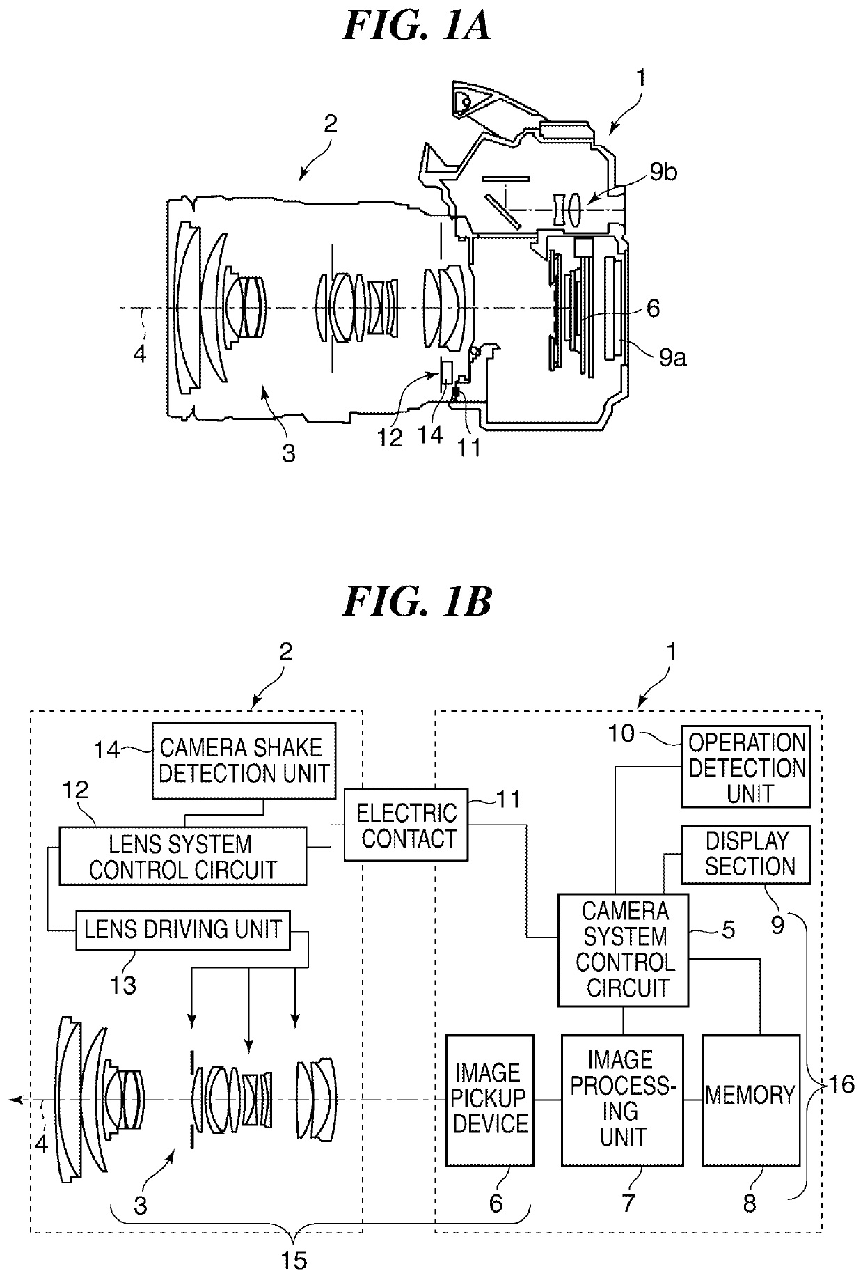
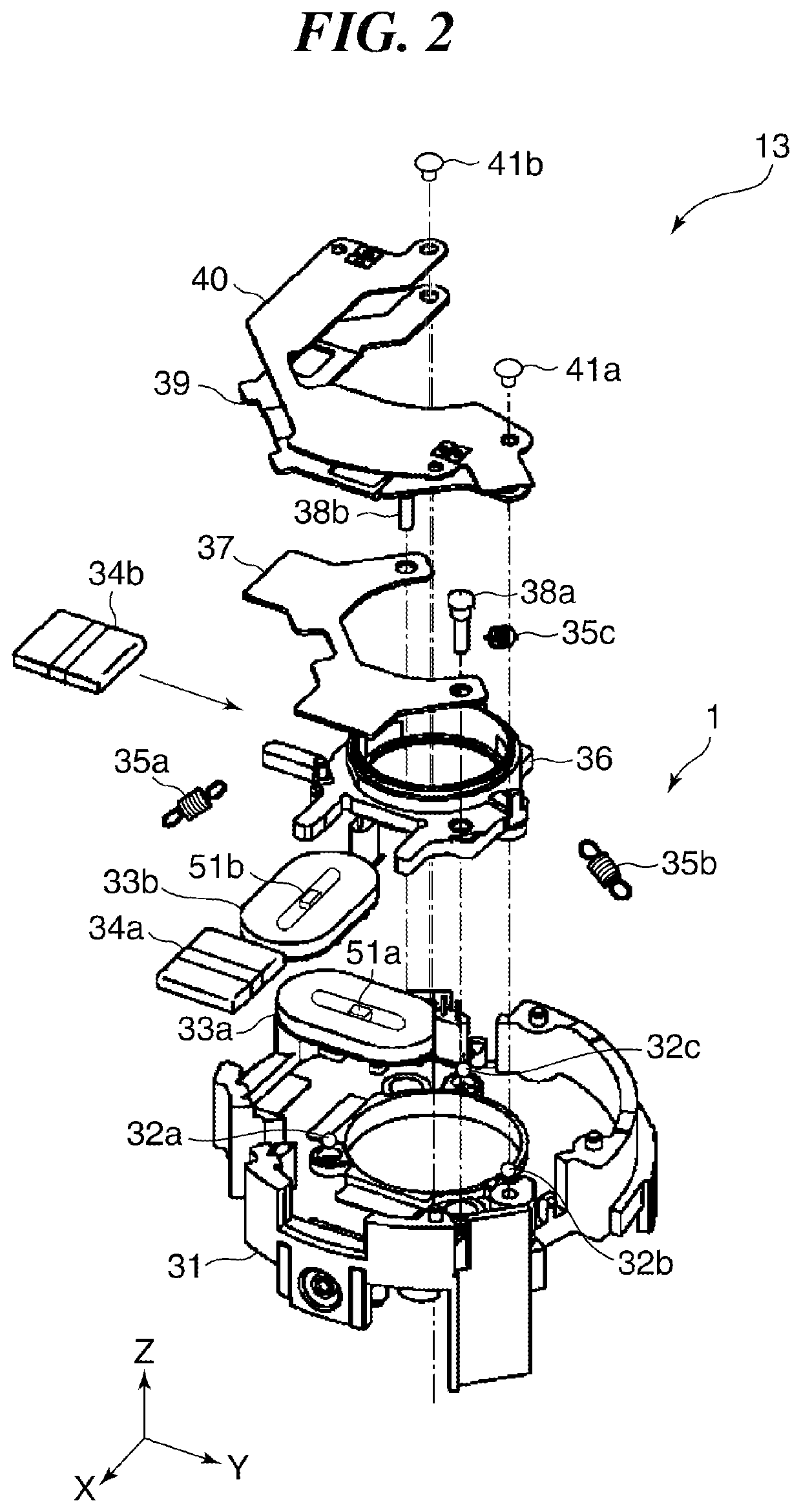
[0054]FIG. 2 is an exploded perspective view showing a part of the lens driving unit 13 in FIG. 1 that functions as the antivibration device according to the

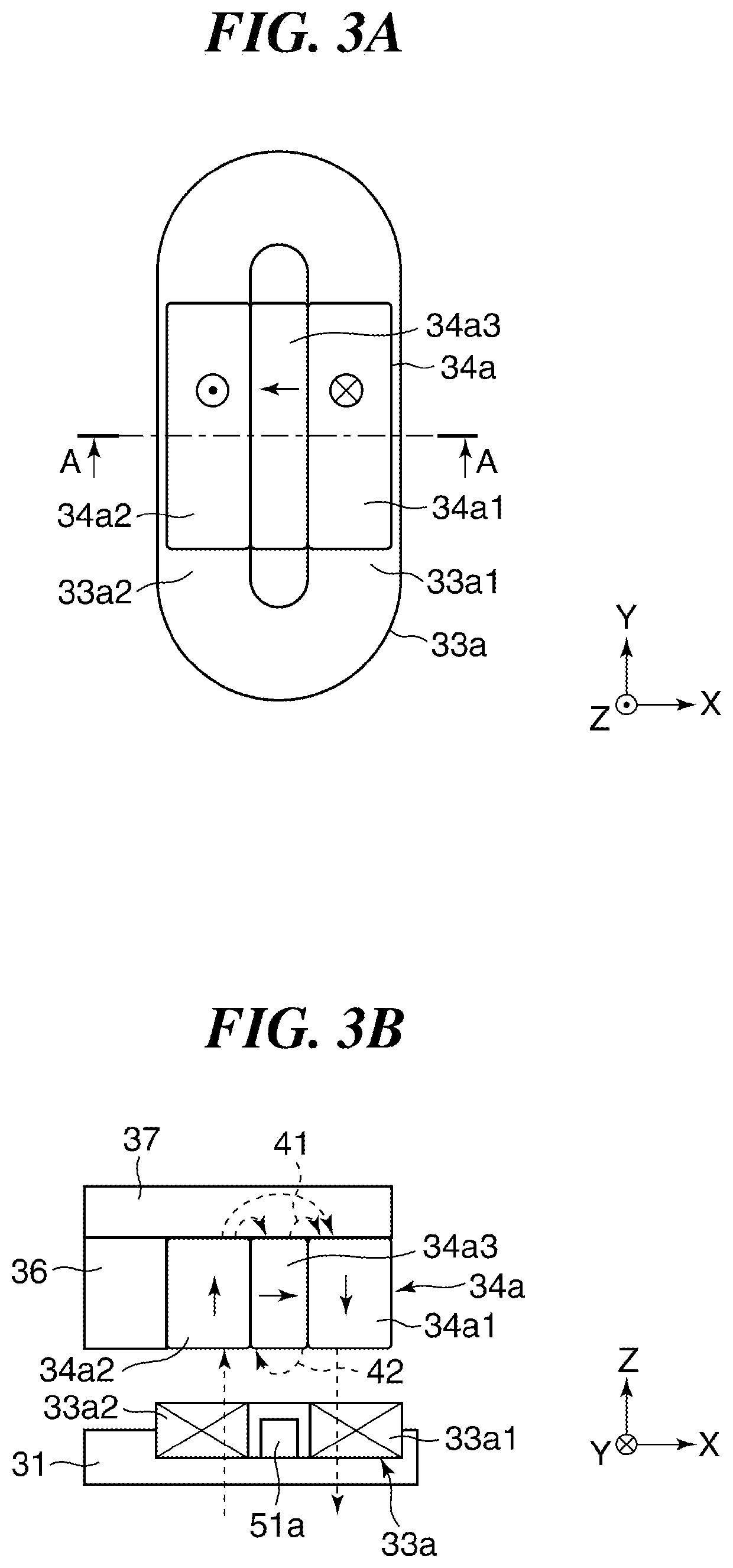
[0055]As shown in FIG. 2, the lens driving unit 13 is provided with a stationary frame 31, a movable frame 36, balls 32a, 32b, and 32c nipped between the stationary frame 31 and the movable frame 36, coils 33a and 33b fixed to the stationary frame 31, and magnet assemblies 34a and 34b fixed to the movable frame 36. Moreover, the movable frame 36 is held resiliently by elastic bodies 35a, 35b, and 35c to the stationary frame 31. A magnet attraction plate (back yoke) 37 is attached to the movable frame 36 with attraction-plate fixing screws 38a and 38b. A moving-frame holding board 39 and an FPC 40 are attached to the movable frame 36 with the FPC fixing screws 41a and 41b. Magnetometric sensors 51a and 51b are respectively provided inside windings of the coils 33a and 33b. These magnetometric sensors 51a and 51b function as posit...

second embodiment

[0098]FIG. 6 is an exploded perspective view showing a part of a lens driving unit 13 that functions as an antivibration device according to the

[0099]In FIG. 6, the same reference number is assigned to the member that has the same function as the member of the lens driving unit 13 that functions as the antivibration device of the first embodiment shown in FIG. 2. The configuration shown in FIG. 6 is provided with sliding shafts 201a, 201b, and 201c, a lock ring 202, a lock-ring drive motor 203, an anti-rotation bar 204, a fixed yoke 205, a positioning pin 206, screws 207a, 207b, 208, 212a, 212b, and 214, LEDs 209a and 209b, an opposition yoke 210, a shading plate 211, a relay FPC 213, and a photointerrupter 215. Coils 33a and 33b, LEDs 209a and 209b are fixed to a movable frame 36 and move together with the movable frame 36. The relay FPC 213 is fixed to a stationary frame 31 with the screw 214. Electric power is supplied to the LEDs 209a and 209b, the photointerrupter 215, and the ...

third embodiment

[0112]Hereinafter, an antivibration device will be described with reference to FIG. 7.

[0113]FIG. 7 is different from that in FIG. 6 at the configuration of the magnetic circuit and the others are common. Accordingly, only the difference from FIG. 6 will be described about FIG. 7.

[0114]FIG. 7 is an exploded perspective view showing a part of a lens driving unit 13 that functions as an antivibration device according to the third embodiment.

[0115]Although the schematic configuration of the antivibration device shown in FIG. 7 is similar to that shown in FIG. 6, a magnet assembly 34c is arranged at a position opposite to the magnet assembly 34a across the coil 33a, and a magnet assembly 34d is arranged at a position opposite to the magnet assembly 34b across the coil 33b. This improves the magnetic flux density more.

[0116]A preferable arrangement of magnets (magnetization direction) in the magnetic circuit of the third embodiment will be described with reference to FIG. 8B. FIG. 8B sho...


PUM


Abstract

A drive apparatus comprising a stationary frame with a coil, a movable frame with a magnetic circuit held movably in a direction orthogonal to a first direction, and a drive unit that moves the movable frame by applying electric current to the coil. The magnetic circuit is constituted by aligning a first magnet having a magnetization direction parallel to the first direction, a second magnet having a magnetization direction opposite to the first magnet, and a third magnet between the first and second magnets in a direction orthogonal to the first direction. The third magnet has a magnetization direction that has a pole in the same direction of the poles of the first and second magnets when viewed from the coil side. The side spaces of the first and second magnets opposite to the third magnet are occupied by material whose magnetic permeability is lower than the magnets.

Description

BACKGROUND OF THE INVENTIONField of the Invention[0001]The present invention relates to a drive apparatus that is characterized in a magnetic circuit employed by a drive unit.Description of the Related Art[0002]Many image pickup apparatus and photographing lenses are provided with an antivibration device for stabilizing an image (i.e., for compensating image blur due to a camera shake) as performance of image pickup apparatuses increases in recent years. In many antivibration devices, a drive unit uses a voice coil motor (hereinafter referred to as a “VCM”) and is so configured that a coil is arranged on one of a movable part and stationary part and a magnet is arranged on the other. Moreover, a driving apparatus that is capable of driving a target within a wider range is desired in order to increase performance of an antivibration device.[0003]A drive unit of an antivibration device disclosed in Japanese Laid-Open Patent Publication (Kokai) No. H8-211436 (JP H8-211436A) has what is...

Claims


Application Information

Patent Timeline
Patent Type & Authority Patents(United States)
IPC IPC(8): G02B7/04H02K41/035H04N5/232G03B5/00G02B27/64
CPCH02K41/0354G02B27/646G03B5/00H02K41/0356H04N5/23209H04N5/23258H04N5/23287G03B2205/0015G03B2205/0038G03B2205/0069H04N23/68H04N23/687H04N23/663H04N23/6812
Inventor KIMURA, MASAFUMISATO, KYOSUKE
Owner CANON KK
Why Eureka
Try Eureka