A micro power generation device

A power generation device and micro technology, applied in electromechanical devices, electrical components, etc., can solve the problems of energy density not meeting the requirements, complex process, etc., to achieve the effect of simple structure, reduced module volume, and improved stress

Active Publication Date: 2019-02-26
QINGDAO AUGREENER ELECTRONICS TECH
View PDF8 Cites 0 Cited by
  • Summary
  • Abstract
  • Description
  • Claims
  • Application Information

AI Technical Summary

Problems solved by technology

With the development of miniaturization, the energy density of existing micro power generation modules often cannot meet the requirements, and the process is complicated

Method used


Image

  • A micro power generation device
  • A micro power generation device
  • A micro power generation device

Examples


Embodiment 1

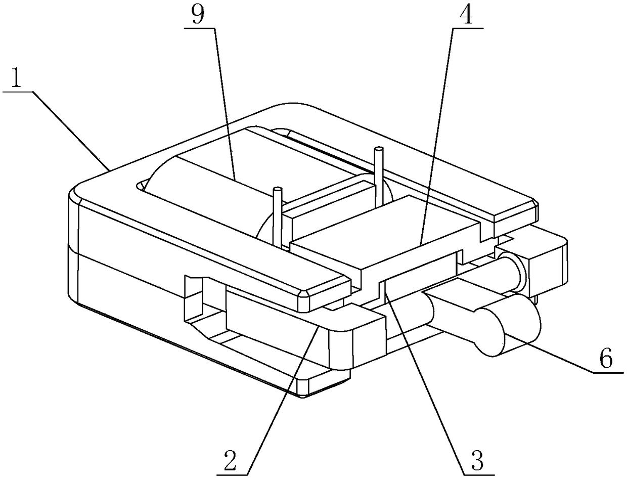
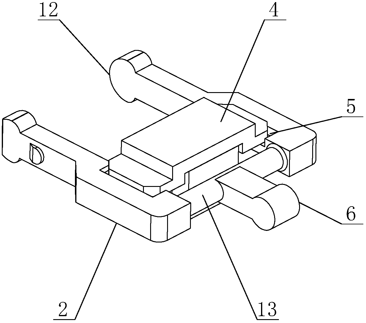
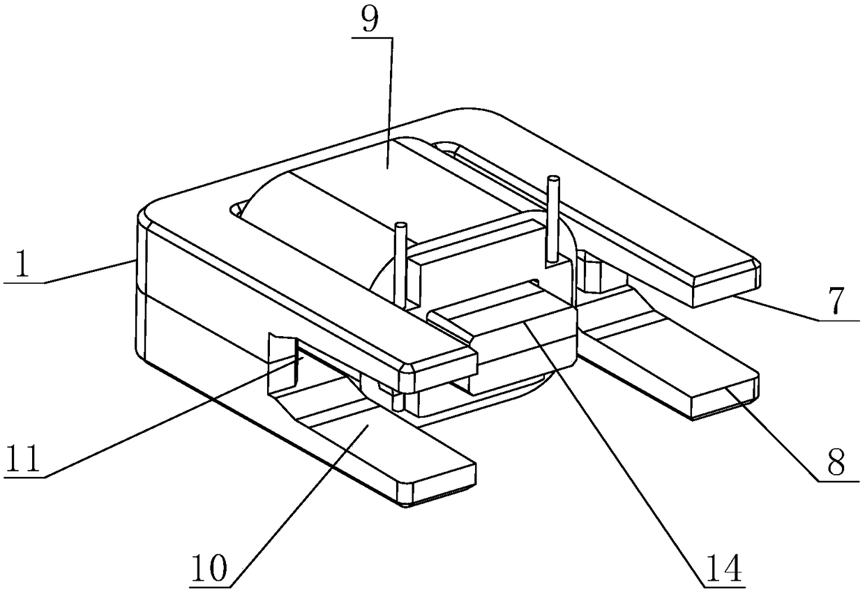
[0032]A miniature power generation device includes moving parts and an iron core 1 matched with the moving parts. The moving parts include a magnet frame 2, a magnet 3 and a magnetically conductive sheet 4. Mounting grooves 5 are arranged on both sides of the magnet frame 2, and a magnetically conductive sheet 4 is installed in the mounting groove 5. The magnetically conductive sheet includes an upper magnetically conductive sheet. A sheet 41 and a lower magnetically conductive sheet 42, the magnet 3 is located between the two magnetically conductive sheets 4. One end of the magnet frame 2 is provided with an operating head 6, and one end of the magnet frame 2 near the operating head 6 is provided with an elastic deformation zone 13, which can provide torsional elastic deformation in a small and micro range, play an elastic buffering role, and reduce the impact of the toggling speed. The influence of the moving speed of the moving parts makes the overall performance of the mic...

Embodiment 2

[0034] A miniature power generation device includes moving parts and an iron core 1 matched with the moving parts. The moving parts include a magnet frame 2, a magnet 3 and a magnetically conductive sheet 4. Mounting grooves 5 are arranged on both sides of the magnet frame 2, and a magnetically conductive sheet 4 is installed in the mounting groove 5. The magnetically conductive sheet includes an upper magnetically conductive sheet. A sheet 41 and a lower magnetically conductive sheet 42, the magnet 3 is located between the two magnetically conductive sheets 4. One end of the magnet frame 2 is provided with an operating head 6, and one end of the magnet frame 2 near the operating head 6 is provided with an elastic deformation zone 13, which can provide torsional elastic deformation in a small and micro range, play an elastic buffering role, and reduce the impact of the toggling speed. The influence of the moving speed of the moving parts makes the overall performance of the mi...


PUM


Abstract

The invention discloses a miniature power generation device, and relates to the technical field of a power generation device. The miniature power generation device comprises a moving part and an iron core, wherein the iron core is matched with the moving part, the moving part comprises a magnet rack, installation grooves are formed in the upper side and the lower side of the magnet rack, magnetic conduction sheets are arranged in the installation grooves, a magnet is arranged between the two magnetic conduction sheets, an operation head is arranged at one end of the magnet rack, one end, far away from the operation head, of the magnet rack extends to the iron core, the magnet rack rotates around the iron core, a limitation device is arranged on the iron core and is used for limiting the rotation of the moving part, an upper moving stop point and a lower moving stop point are formed on the limitation device, a coil winds around the iron core, and a main magnetic path, an upper branch magnetic path and a lower branch magnetic path are separately matched with different parts of the moving part. The miniature power generation device has the advantages of simplicity in structure, the module volume is reduced, the arrangement mode of a magnetic path part coordination region is changed to multi-short-line dispersion from original single-long-line dispersion along a moving direction, the power density is effectively improved, and the production process is substantially simplified.

Description

technical field [0001] The invention relates to the technical field of power generation devices, in particular to a micro power generation device. Background technique [0002] In recent years, with the development of passive wireless devices, more and more new usage requirements have been put forward, and the existing generator models do not meet some new usage requirements, so it is imminent to develop a new type of generator. With the development of miniaturization, the energy density of existing micro power generation modules often cannot meet the requirements, and the process is complicated. Contents of the invention [0003] In order to solve the deficiencies in the prior art, the present invention provides a miniature power generation device, which has a simple structure and reduces the module volume. The arrangement of the matching areas of the magnetic circuit components is changed from the original single long row scattered along the moving direction to multi-sho...

Claims


Application Information

Patent Timeline
Patent Type & Authority Patents(China)
IPC IPC(8): H02K35/02
CPCH02K35/02
Inventor 安邦
Owner QINGDAO AUGREENER ELECTRONICS TECH
Why Eureka
Try Eureka