
Control device for vibration generation device, electronic apparatus, and method of controlling vibration generation

a technology of vibration generation and control device, which is applied in the direction of electronic commutators, dynamo-electric converter control, dc motor rotation control, etc., to achieve the effect of smooth stoppage of reverse rotation operation and improving responsivity

Active Publication Date: 2021-10-26
SEIKO INSTR INC
View PDF17 Cites 0 Cited by
  • Summary
  • Abstract
  • Description
  • Claims
  • Application Information

AI Technical Summary

Benefits of technology

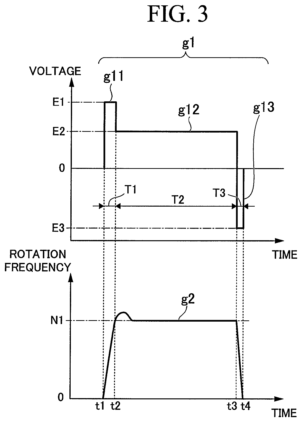
[0024]According to an aspect of the invention, it is possible to increase the start-up torque of the vibration generation device to shorten the time until the rotation frequency in the steady operation of the vibration generation device is reached.
[0025]Further, according to an aspect of the invention, it becomes possible to rapidly stop the vibration generation device, and it is possible to propagate the lively vibration to the user. Further, according to an aspect of the invention, it is possible to generate a variety of vibration patterns using the vibrations of the vibration generation device.
[0027]Further, according to an aspect of the invention, it is possible to obtain an advantage of improving the responsivity (start-up, stoppage).
[0028]Further, according to an aspect of the invention, it is possible to smoothly stop the reverse rotation operation.

Problems solved by technology

In this case, since it is difficult for the user to judge whether or not the button is pressed (set to the ON state), it has been getting started to propagate the vibration to the finger in order to notify the user of the fact that the button has been pressed.

Method used


Image

  • Control device for vibration generation device, electronic apparatus, and method of controlling vibration generation
  • Control device for vibration generation device, electronic apparatus, and method of controlling vibration generation
  • Control device for vibration generation device, electronic apparatus, and method of controlling vibration generation

Examples


modified examples

[0189]Then, modified examples of the control device of the vibration generation device will be described.

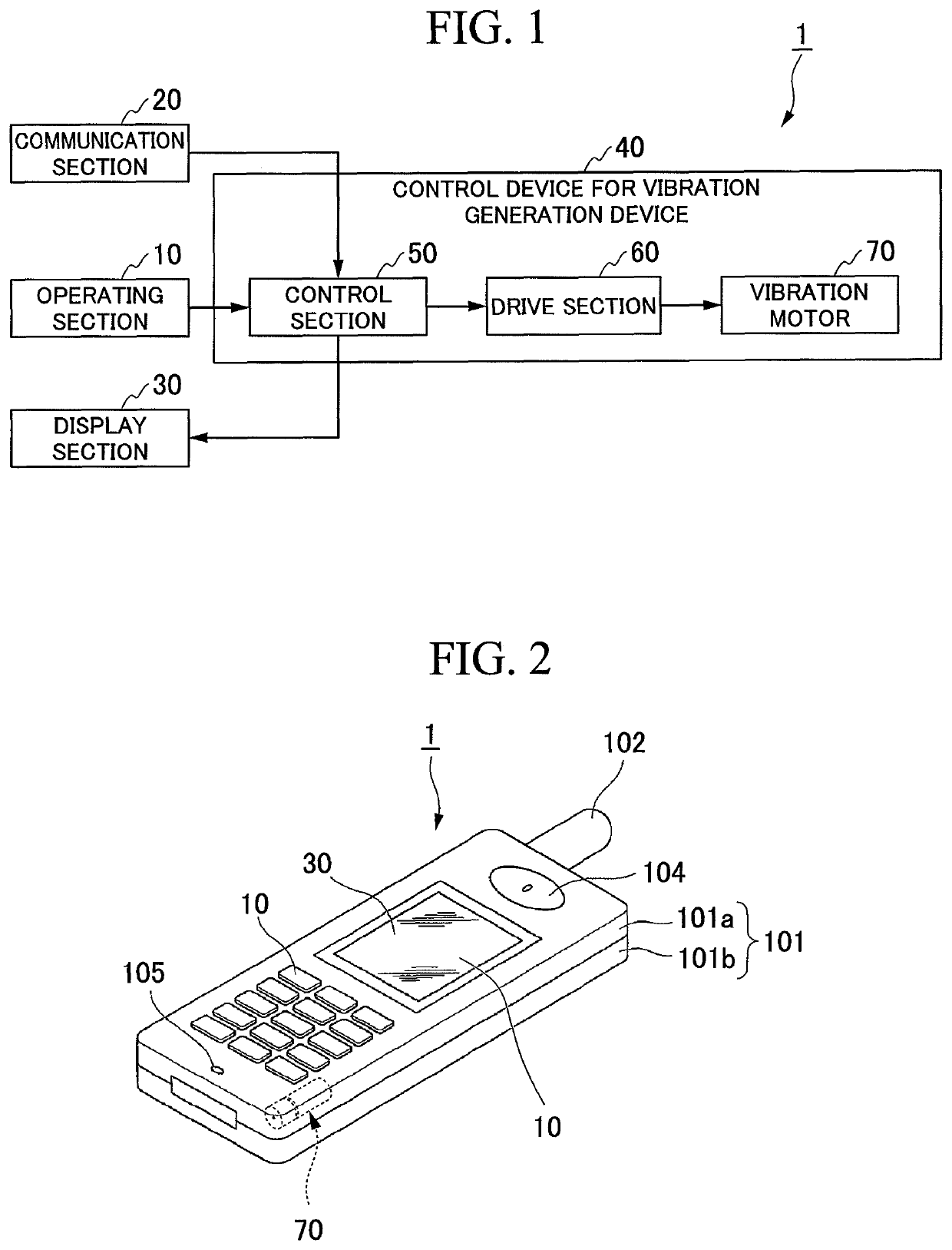
[0190]FIG. 20 is a block diagram showing a configuration example of an electronic apparatus 1A including a control device 40A for a vibration generation device according to a modified example of the present embodiment. As shown in FIG. 20, the electronic apparatus 1A is provided with the operating section 10, the communication section 20, the display section 30, and a control device 40A for the vibration generation device. The control device 40A for the vibration generation device is provided with a control section 50A (the control section), the drive section 60 (the drive section), the vibration motor 70 (the vibration generation device), a resistor R, and a switch SW. It should be noted that the functional sections having the same functions as in the control device 40 for the vibration generation device are denoted by the same reference symbols, and the description thereof will...


PUM


Abstract

A vibration generation device includes a stator, and a rotor rotatable around a predetermined axis with respect to the stator and having a weight having a gravity center at a position shifted from the predetermined axis. A control section controls a start-up period maximum voltage value, which is a maximum voltage value of a drive signal to be applied to the vibration generation device in a start-up period, to become larger than a steady operation period voltage value, which is a voltage value of the drive signal to be applied to the vibration generation device in a steady operation period. The control section selects at least one of a pluraity of voltage values as the steady operation period voltage value and sets the duration of the start-up period based on the steady operation period voltage value selected.

Description

FIELD OF THE INVENTION[0001]The present invention relates to a control device for a vibration generation device, an electronic apparatus, and a method of controlling a vibration generation device.[0002]Priority is claimed on Japanese Patent Application No. 2016-244237, filed on Dec. 16, 2016, and Japanese Patent Application No. 2017-201984, filed on Oct. 18, 2017, the contents of which are incorporated herein by reference.BACKGROUND ART[0003]In the information equipment such as a cellular phone or a tablet PC, there are used vibrations as measures for transmitting information such as incoming, mail reception, and alarm notification to the user. Further, in recent years, vibrations are used as measures for transmitting a variety of types of information to the user also in a touch panel display or the like used in AV equipment, gaming equipment, a bank ATM (automatic teller machine), and so on.[0004]As the vibration generation device, there is adopted, for example, a vibration motor (...

Claims


Application Information

Patent Timeline
Patent Type & Authority Patents(United States)
IPC IPC(8): H02K33/00H02K7/075H02P6/17H02P7/03H02P25/032H02K7/06H02P3/12H02P1/02H02P3/10H02P6/30
CPCH02P7/05H02K7/061H02P1/028H02P3/10H02P3/12H02P6/30H02P25/032H02P29/20H02P29/40
Inventor IINO, AKIHIRO
Owner SEIKO INSTR INC
Learn More