Coupling

a technology of coupling and accessory mount, which is applied in the direction of muzzle attachment, etc., can solve the problems of adapter loosening on the barrel, inability to easily be carried out with one hand, etc., and achieve the effect of preventing unintentional loosening of the coupling

Active Publication Date: 2021-10-26
A TEC HLDG
View PDF12 Cites 7 Cited by
  • Summary
  • Abstract
  • Description
  • Claims
  • Application Information

AI Technical Summary

Benefits of technology

[0017]It is an object of the invention to provide a coupling for a firearm accessory which may quickly be mounted upon a muzzle of a firearm wherein only axial and rotative one hand movement is required to mount and lock the adapter on the muzzle of the firearm.
[0018]A further object of the invention is to provide a coupling which will not loosen unintentionally during operation and / or firing of the firearm.
[0020]The present invention relates to a coupling for quick and easy attachment and detachment of a firearm accessory to a muzzle of the firearm, where the firearm accessory, for instance, may be a flash suppressor or muzzle brake, a silencer, a grenade launcher, blank adapter, or the like, and where the coupling is provided with means to prevent unintentional loosening of the coupling.
[0021]The coupling for quick and easy attachment and detachment of a firearm accessory to a firearm according to the present invention comprises a female member and a male member, where the female member is provided with a throughgoing bore and further is provided with a number of successive threaded portions and unthreaded portions around a circumference of the throughgoing bore, where the male member around an outer circumference is provided with the same number of successive threaded portions and unthreaded portions as the female member, the female member further being provided with a groove arranged around an outer circumference of the female member and a through-going slit extending from the groove to an end of the female member, the male member being provided with a number of recesses arranged around an outer circumference of the male member, a resilient lock element being arranged in the groove.
[0038]The female member of the coupling member may be provided with at least one abutment shoulder around the circumference of the throughgoing bore, where the at least one abutment shoulder will cooperate with at least one abutment shoulder provided around an outer circumference of the male member. The abutment shoulders will then restrict the distance the male member can be moved along a longitudinal direction of the female member and further provide a correct adjustment or setting of the threaded portions of the female and male members, such that male member can be rotated without further adjustment. The abutment shoulders of the female and male members will also form a tight connection in the coupling device when the female and male members are locked together.

Problems solved by technology

It cannot easily be accomplished with one hand, and the possibility of the adapter loosening on the barrel exists in the event the threaded lug locking member unloosens due to vibration occurring during firearm operation.

Method used


Image

  • Coupling
  • Coupling
  • Coupling

Examples


Embodiment Construction

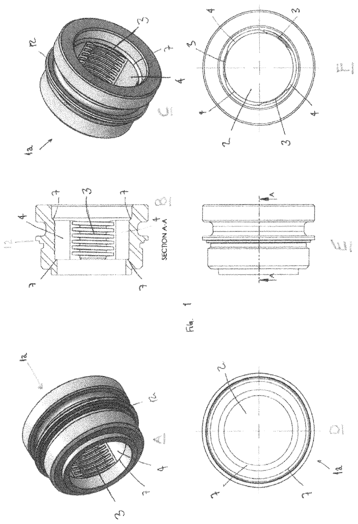
[0054]FIG. 1 shows a female member 1a of the coupling 1 according to the present invention, where the female member 1a is provided with a throughgoing bore 2. A diameter of the throughgoing bore 2 will vary over the longitudinal length of the female member 1a, as will be described below.

[0055]Three threaded portions 3 and three unthreaded portions 4 are provided around a circumference of the throughgoing bore 2, where the threaded portions 3 and the unthreaded portions 4 are arranged in turns, i.e. a threaded portion 3 is followed by an unthreaded portion 4 and an unthreaded portion 4 is followed by a threaded portion 3. Each of the threaded portions 3 and each of the unthreaded portions 4 are displaced 60 degrees relative each other.

[0056]Furthermore, the female member 1a is provided with two abutment shoulders 7 extending around the whole circumference of the throughgoing bore 2, where the first abutment shoulder 7 is arranged in front of the threaded and unthreaded portions 3, 4 ...


PUM


Abstract

The present invention relates to a coupling for quick and easy attachment and detachment of a firearm accessory to a muzzle of a firearm, the coupling including a female member and a male member, where the female member is provided with a throughgoing bore and further is provided with a number of successive threaded portions and unthreaded portions around a circumference of the throughgoing bore, wherein the male member around an outer circumference is provided with the same number of successive threaded portions and unthreaded portions as the female member, the female member further being provided with a groove arranged around an outer circumference of the female member and a through-going slit extending from the groove to an end of the female member, the male member being provided with a number of recesses arranged around an outer circumference of the male member, a resilient lock element being arranged in the groove.

Description

FIELD OF THE INVENTION[0001]The present invention relates generally to firearms, accessories and accessory mounts for firearms, and particularly to muzzle end accessories and accessory mounts for firearms.BACKGROUND OF THE INVENTION[0002]The term “firearms” includes hand guns (including revolvers and pistols), long guns (including rifle and shotguns), automatic weapons (including machine guns, submachine guns and automatic rifles), and air-operated firearms.[0003]It is often desirable to mount an accessory such as a flash suppressor or muzzle brake, silencer, grenade launcher, blank adapter, or the like, upon the muzzle or end of gun barrels. Such accessories are usually mounted upon an adapter which constitutes a coupling for attaching the accessory to the gun barrel.[0004]Muzzle end mounted firearm accessories are available for attachment to the barrel of firearms to obtain various effects when the firearm is operated. Silencers are an example of such an accessory and include baff...

Claims


Application Information

Patent Timeline
Patent Type & Authority Patents(United States)
IPC IPC(8): F41A21/32F41A21/34
CPCF41A21/325F41A21/34
Inventor WINTERSETH, HALLVARDJOHANSEN, ANDERS ECKHOFF
Owner A TEC HLDG
Why Eureka
Try Eureka