Water heating system including multi-function heat source apparatus

a multi-functional, water heating technology, applied in the field of water heating systems, can solve the problems of controlling hot water supply to suppress the lowering of space-heating function of space-heating water heaters, and achieve the effect of suppressing the lowering of space-heating function and hot water supply power

Active Publication Date: 2021-10-19
NORITZ CORP
View PDF20 Cites 2 Cited by
  • Summary
  • Abstract
  • Description
  • Claims
  • Application Information

AI Technical Summary

Benefits of technology

[0004]In control for varying the number of water heaters to perform hot water output operations in accordance with an amount of hot water supply as in Japanese Patent Publication No. 8-30607, a plurality of water heaters are categorized into a main water heater which outputs hot water throughout a low flow-rate period and a high flow-rate period and a sub water heater which supplementarily outputs hot water only while a flow rate is high. In a system configuration in which a plurality of water heaters of the same type are connected in parallel as in Japanese Patent Publication No. 8-30607 and Japanese Patent No. 3707437, progress of deterioration in a specific water heater is generally avoided by designating by rotation a main water heater among the plurality of water heaters in control above.
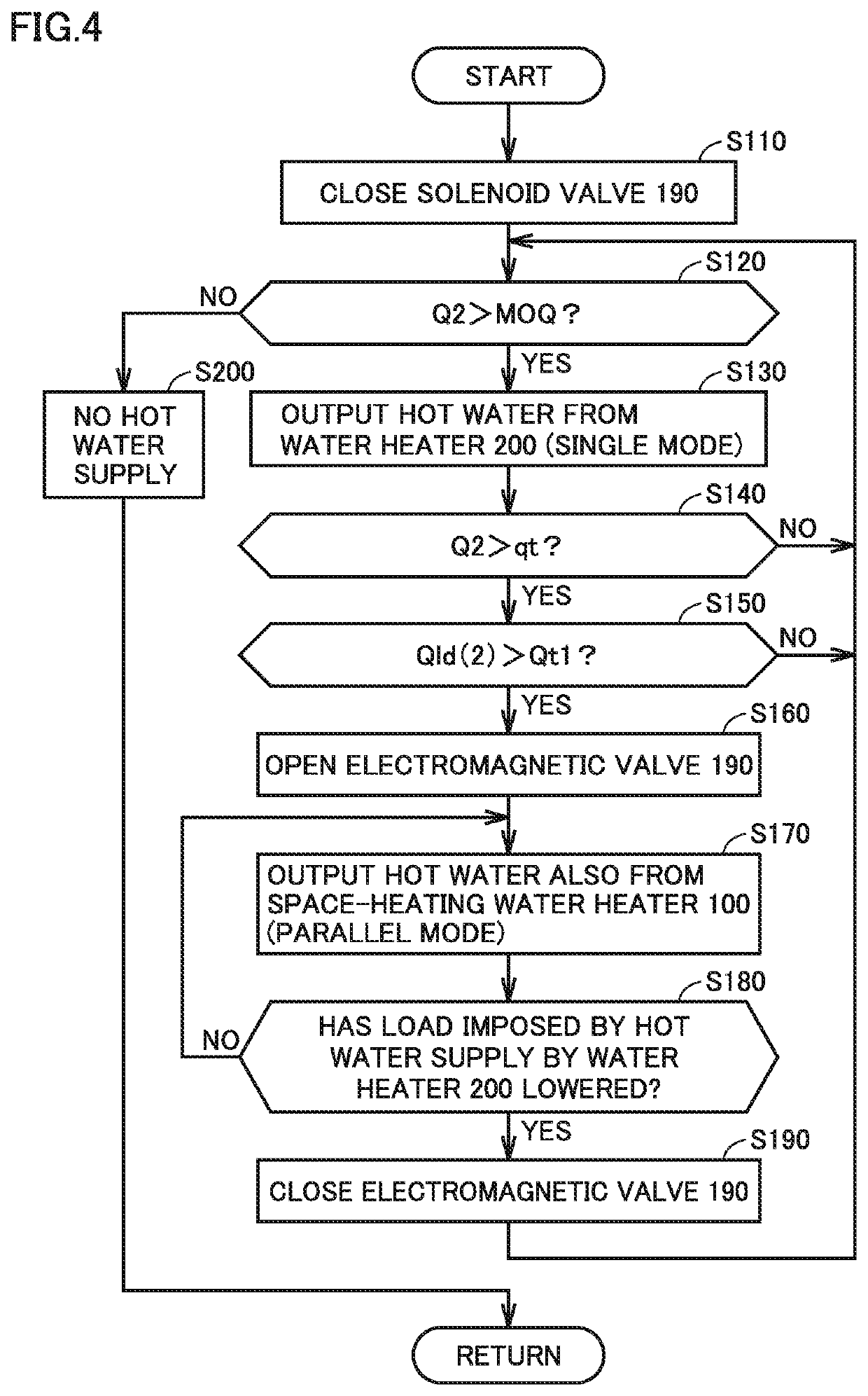
[0008]According to the water heating system, a hot water supply operation is started by outputting hot water from the second heat source apparatus alone, and the hot water supply operation by the first heat source apparatus which heats water by using some of heating power for space-heating is performed in such a manner that hot water is output only when a load imposed by hot water supply by the second heat source apparatus is high. Therefore, hot water supply power (a maximum amount of hot water supply) can be increased by hot water output from the first and second heat source apparatuses in parallel, and hot water output from the first heat source apparatus (multi-function heat source apparatus) can be minimized. Therefore, lowering in space-heating function of the first heat source apparatus can be suppressed.

Problems solved by technology

Specifically, unlike Japanese Patent Publication No. 8-30607 on the premise that a plurality of water heaters of the same type are connected in parallel, control of hot water supply to suppress lowering in space-heating function of the space-heating water heater becomes an issue.

Method used


Image

  • Water heating system including multi-function heat source apparatus
  • Water heating system including multi-function heat source apparatus
  • Water heating system including multi-function heat source apparatus

Examples


first embodiment

[0024]FIG. 1 is a block diagram illustrating a configuration of a water heating system according to an embodiment of the present invention.

[0025]Referring to FIG. 1, a water heating system 10 according to the present embodiment includes a space-heating water heater 100 representing a hot-water-heating heat source apparatus with both of a space-heating function and a hot water supply function, a water heater 200 dedicated for hot water supply, a water entry pipe 20, and a hot water delivery pipe 40.

[0026]Space-heating water heater 100 includes a heating mechanism 101 and a hot water supply circuit 110. Hot water supply circuit 110 has a space-heating function by circulating and feeding a heat medium heated by heating mechanism 101 to and from a space-heating terminal 300. Hot water supply circuit 110 further has a hot water supply function to output hot water to hot water delivery pipe 40 by heating at least some of low-temperature water introduced from water entry pipe 20 with a hea...

second embodiment

[0102]Lowering in space-heating power is suppressed by fixing water heater 200 as the main water heater to suppress an opportunity of hot water output by space-heating water heater 100 in the water heating system described in the first embodiment. Consequently, it is a concern that water stays for a long period of time in hot water supply circuit 110 of space-heating water heater 100 due to absence of hot water output by space-heating water heater 100 for a long period of time.

[0103]In the configuration example in FIG. 3, water may stay for a long period of time in a path from node N2 on water entry pipe 20 via water entry pipe 112 and secondary-side path 152 in heat exchanger 150 for hot water supply to solenoid valve 190 in hot water delivery pipe 115 (which is also referred to as a “retention path” below) as a result of closing of solenoid valve 190. Control for automatically draining such stagnant water by sensing presence of stagnant water so as to avoid retention of water in h...

third embodiment

[0130]Restriction of a flow rate in hot water supply circuit 110 (space-heating water heater 100) in the parallel mode in which hot water is output from both of water heater 200 and space-heating water heater 100 will be described in a third embodiment. A ratio of a flow rate between hot water supply circuits 110 and 210 follows flow rate characteristics attributed to a flow path loss in the hot water supply path in the hot water supply operation in the parallel mode as described above.

[0131]FIG. 9 is a conceptual graph illustrating flow rate characteristics in each of hot water supply circuits 110 and 210 in the water heating system according to the third embodiment. The abscissa in FIG. 9 represents a flow rate (L / min.) and the ordinate represents a pressure (kPa). The pressure is varied by a pressure of supplied clean water and the number and positions of hot water supply faucets which are opened.

[0132]Referring to FIG. 9, flow rate characteristics CGQ1 and CGQ2 exhibit flow rate...


PUM


Abstract

When a hot water supply operation is started, a single mode is used in which hot water is output only from a second hot water supply circuit of a water heater, by cut-off of a flow path in a first hot water supply circuit of a space-heating water heater by a cut-off mechanism. When a load imposed by hot water supply by the second hot water supply circuit increases during the hot water supply operation in the single mode, the cut-off mechanism is opened to start hot water output from the first hot water supply circuit and a hot water supply operation in a parallel mode is performed in which hot water is output from both of the first hot water supply circuit and the second hot water supply circuit.

Description

BACKGROUND OF THE INVENTIONField of the Invention[0001]This invention relates to a water heating system and more particularly to a water heating system in which a multi-function heat source apparatus capable of simultaneous operations of space-heating and hot water supply and a heat source apparatus with a hot water supply function are connected in parallel.Description of the Background Art[0002]Japanese Patent Publication No. 8-30607 discloses a control method for increasing and decreasing the number of water heaters which perform hot water output operations in connection with a plurality of water heaters connected in parallel. Japanese Patent No. 3707437 discloses a system configuration in a water heating system including two water heaters connected in parallel, in which a controller of each water heater controls each water heater with a signal transmitted between the water heaters through an external cable without a system controller.[0003]A space-heating water heater capable of ...

Claims


Application Information

Patent Timeline
Patent Type & Authority Patents(United States)
IPC IPC(8): F24D19/10F24D3/08F24D12/02F24D17/00
CPCF24D19/1066F24D3/08F24D12/02F24D17/0036F24D2200/00F24D2220/0292F24D2220/042F24D2220/044Y02B10/20Y02B10/70Y02B30/00
Inventor KUSACHI, RENAATOBE, YOSHIFUMITSUDA, NAOKIIWANAMI, KEIICHIROMORIMOTO, HIROSHIKAGEYAMA, AKIHISAYOKOYAMA, TAKEHITOYOKOYAMA, MIDORI
Owner NORITZ CORP
Why Eureka
Try Eureka