
Driving method and driving device using the same

a driving device and driving method technology, applied in the direction of magnetic cores of transformers/inductances, fixed transformers or mutual inductances, pulse techniques, etc., can solve problems such as large magnetic core conflicts with miniaturization

Active Publication Date: 2021-10-12
SYNC POWER CORP
View PDF5 Cites 0 Cited by
  • Summary
  • Abstract
  • Description
  • Claims
  • Application Information

AI Technical Summary

Benefits of technology

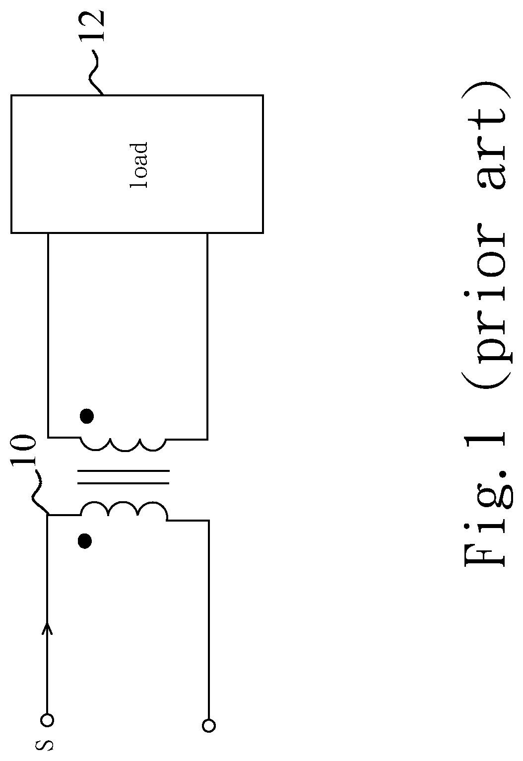
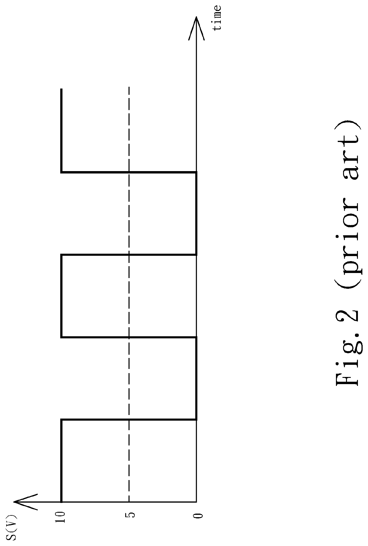
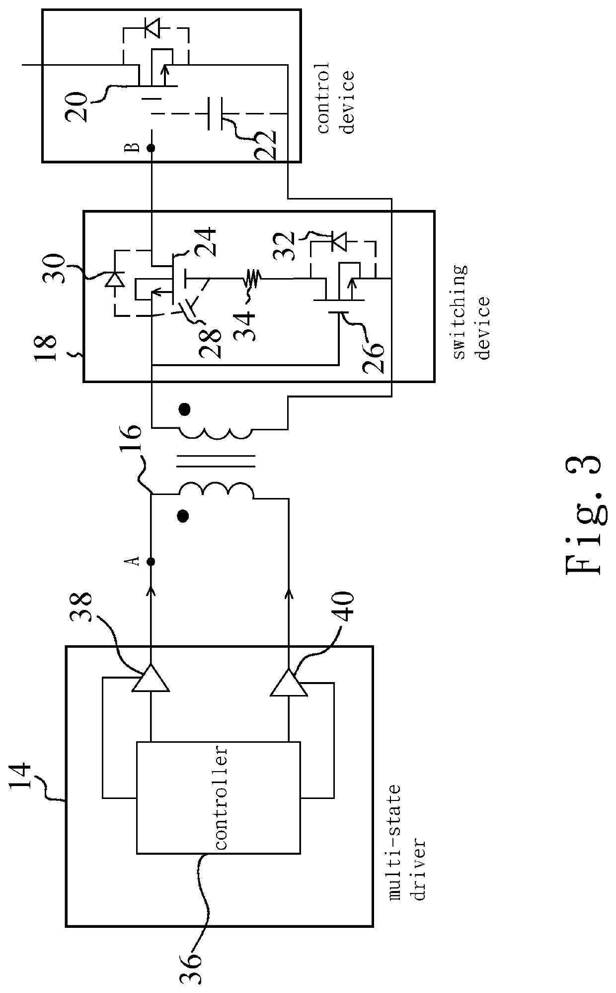
[0004]The primary objective of the present invention is to provide a driving method and a driving device using the same, by using a small magnetic core pulse transformer configured in connection to a multi-state driver to avoid the shortcomings of a traditional pulse transformer where no DC bias can be present at the windings, and a serial capacitor is thus required to filter out the DC bias in the driver, but at the cost of erroneous operations during rapid driver signal duty change (rapid load change).
[0005]Another objective of the present invention is to provide a driving method and a driving device using the same, which use the multi-state driver to allow the pulse transformer core into light saturation without resulting in large drive current, and utilize a high impedance state to take advantage of the residual magnetic core flux for better pulse transformer coupling when the driver signal is reversed, thus a smaller transformer core size can be used.
[0006]The third objective of the present invention is to provide a driving method and a driving device using the same, which has the ability to keep pulse transformer secondary side in the low impedance state when the primary side is in the low impedance state.
[0007]To achieve the abovementioned objectives, the present invention provides a driving method for controlling a pulse transformer, a secondary winding of the pulse transformer is electrically connected to a control device, and the driving method comprising: delivering positive charging electrical energy to the primary winding, thereby charging the control device; disconnecting the control device from the secondary winding after the step of charging the control device; and then delivering negative discharging electrical energy to the primary winding and electrically connecting the control device to the secondary winding, thereby discharging the control device, and the primary winding is in a low-impedance state after the step of delivering the negative discharging electrical energy to the primary winding. If even smaller pulse transformer core is desired, after the charging state, the driver is placed into a high impedance state, in which the near saturated flux of magnetic core retain most of its flux as residual, thus offering the discharging driver with an optimal range of operation, so that discharging can be completed more effectively and with less parasitical effects.

Problems solved by technology

However, the large magnetic core conflicts with miniaturization.

Method used


Image

  • Driving method and driving device using the same
  • Driving method and driving device using the same
  • Driving method and driving device using the same

Examples


Embodiment Construction

[0018]Reference throughout this specification to “one embodiment” or “an embodiment” means that a particular feature, structure, or characteristic described in connection with the embodiment is included in at least one embodiment. Thus, the appearances of the phrases “in one embodiment” or “in an embodiment” in various places throughout this specification are not necessarily all referring to the same embodiment. Furthermore, the particular features, structures, or characteristics may be combined in any suitable manner in one or more embodiments. It should be appreciated that the figures are not drawn to scale; rather, these figures are merely intended for illustration.

[0019]Throughout the description and claims, it will be understood that when a component is referred to as being “positioned on,”“positioned above,”“connected to,”“engaged with,” or “coupled with” another component, it can be directly on, directly connected to, or directly engaged with the other component, or interveni...


PUM

PropertyMeasurementUnit
voltageaaaaaaaaaa
voltageaaaaaaaaaa
voltageaaaaaaaaaa

Abstract

A driving method and a driving device using the same are disclosed. The driving method controls a pulse transformer. The secondary winding of the pulse transformer is electrically connected to a control device. Firstly, positive charging electrical energy is delivered to the primary winding, thereby charging the control device. Then, the control device is disconnected from the secondary winding while the primary winding is in a high-impedance state. Finally, negative discharging electrical energy is delivered to the primary winding and the control device is electrically connected to the secondary winding, thereby discharging the control device, and the primary winding is in a low-impedance state after the step of delivering the negative discharging electrical energy to the primary winding.

Description

BACKGROUND OF THE INVENTIONField of the Invention[0001]The present invention relates to driving technology, particularly to a driving method and a driving device using the same.Description of the Related Art[0002]Various applications in the electronics industry require isolation of an electrical signal. One such application, for example, is that of off-line power supplies. In such power supplies, it is necessary to convey information about the status of the output voltage to a power controller. This information is commonly known as an error voltage signal or simply an error signal. More generally, this signal may be characterized as an analog signal. In many power supplies, it is required that the output voltage be electrically isolated from the source of power. If this requirement exists and, if, as is often the case, the power controller is electrically connected to the source of power, then it is necessary that the error signal be conveyed across an electrical isolation boundary....

Claims


Application Information

Patent Timeline
Patent Type & Authority Patents(United States)
IPC IPC(8): H03K17/687H01F27/28H01F27/24H01F19/08
CPCH03K17/687H01F19/08H01F27/24H01F27/28H02M3/33576H02M3/33523H01F2019/085H01F27/42H02P13/12
Inventor YEE, HSIAN-PEIHUANG, CHUN-JEN
Owner SYNC POWER CORP
Learn More