
Rotor assembly for an electrodynamic machine that minimizes mechanical stresses in cooling ducts

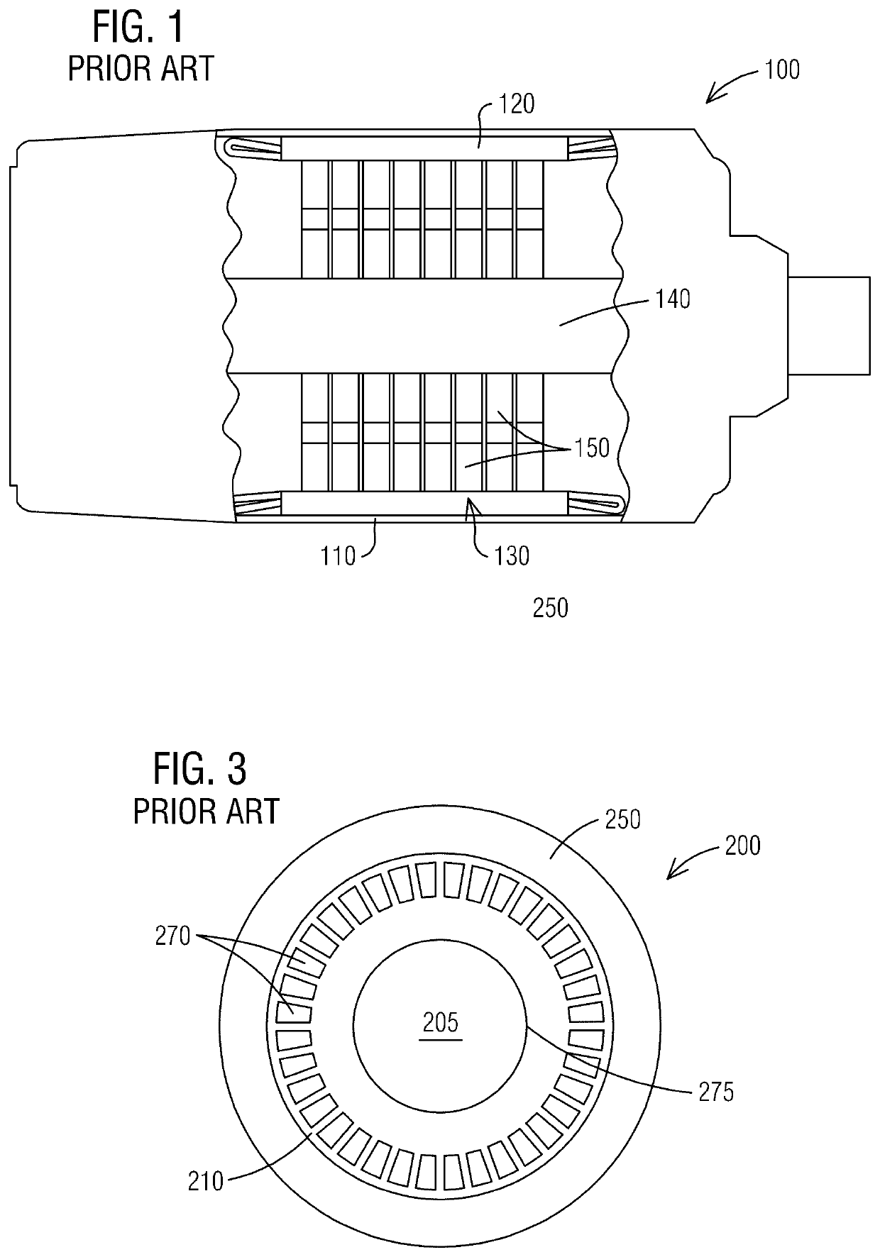
a technology of rotating parts and electrodynamic machines, which is applied in the direction of rotating parts of magnetic circuits, cooling/ventilation arrangements, magnetic circuit shapes/forms/construction, etc., can solve the problems of limiting the amount of power that can be provided by the machine, affecting the operation efficiency of the machine, and generating a large amount of heat during operation. , to achieve the effect of reducing the size of the machin

Active Publication Date: 2021-10-12
INNOMOTICS LLC
View PDF5 Cites 0 Cited by
  • Summary
  • Abstract
  • Description
  • Claims
  • Application Information

AI Technical Summary

Benefits of technology

The present invention is about a rotor assembly for an electrodynamic machine. The rotor has air ducts that provide cooling airflow to the machine. These ducts are part of the rotor's lamination sheets and help with the magnetic circuit and mechanical support structure. Using lighter weight rotors can benefit the machine's mounting arrangement, bearing losses, and dynamics. This allows for cooler running machines and smaller sizes. The rotor provides more airflow while maintaining the same magnetic saturation level and power factor.

Problems solved by technology

Electrodynamic machines typically generate a large amount of heat during operation.
Excessive heat can damage internal components, limit the amount of power that can be provided by the machine, and / or adversely affect the longevity of the machine.
Trapezoidal vents, when optimized for magnetic behavior and airflow are adversely affected by the torque being transmitted, potentially inducing stress beyond the mechanical yield point of the laminated steel sheets.
Round cooling ducts offer poor utilization of material for airflow or magnetic capability.

Method used


Image

  • Rotor assembly for an electrodynamic machine that minimizes mechanical stresses in cooling ducts
  • Rotor assembly for an electrodynamic machine that minimizes mechanical stresses in cooling ducts
  • Rotor assembly for an electrodynamic machine that minimizes mechanical stresses in cooling ducts

Examples


Embodiment Construction

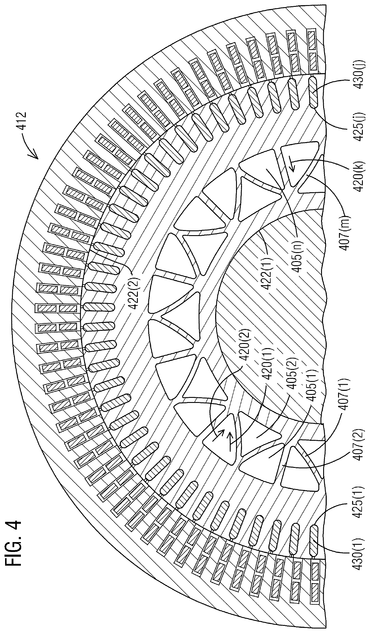
[0020]To facilitate an understanding of embodiments, principles, and features of the present invention, they are explained hereinafter with reference to implementation in illustrative embodiments. In particular, they are described in the context of lighter weight rotors for use in electric machines. An annular array of axial cooling ducts mechanically supported by a plurality of radial and arched structural members are provided in a rotor assembly of an electrodynamic machine to minimize mechanical stresses in the cooling ducts. The plurality of radial and arched structural members define an array of arched or angled supports that readily pass a magnetic flux via an optimal flux path. The annular array of axial cooling ducts offers efficient utilization of material for airflow or magnetic capability. The annular array of axial cooling ducts doesn't induce stress beyond the mechanical yield point of the laminated steel sheets. Embodiments of the present invention, however, are not li...


PUM


Abstract

A rotor assembly for an electrodynamic machine is provided. The rotor assembly comprises a lamination section and an end connector. The lamination section comprises rotor lamination sheets formed to define an annular array of axial cooling ducts mechanically supported by a plurality of radial and arched structural members that define an array of arched or angled supports to readily pass a magnetic flux via an optimal flux path. The lamination section further comprises rotor slots, with rotor conductor bars being disposed in the rotor slots. The end connector is supported by the rotor conductor bars. An axial space is formed in the lamination section by the annular array of axial cooling ducts for guiding a cooling fluid flow in an axial direction through the rotor assembly.

Description

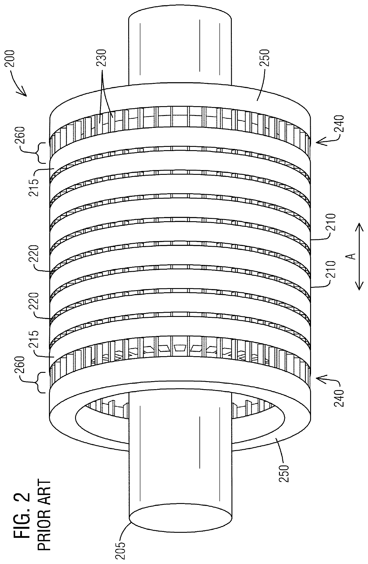
BACKGROUND1. Field[0001]Aspects of the present invention generally relate to a rotor assembly for an electrodynamic machine that minimizes mechanical stresses in cooling ducts.2. Description of the Related Art[0002]Electrodynamic machines typically generate a large amount of heat during operation. Excessive heat can damage internal components, limit the amount of power that can be provided by the machine, and / or adversely affect the longevity of the machine. Electrodynamic machines may have fans or radial and / or axial vents that can remove at least some heat from the machine by drawing cooling air through various passageways in the machine.[0003]Air cooled or gas cooled induction machines, including induction motors and generators, typically employ axial vents for cooling purposes formed in a rotor assembly of the machine. The rotor assembly of an induction machine can be designed as a squirrel cage rotor, such as for example a fabricated copper squirrel cage rotor. The squirrel cag...

Claims


Application Information

Patent Timeline
Patent Type & Authority Patents(United States)
IPC IPC(8): H02K9/14H02K1/32H02K17/16H02K1/28H02K5/04H02K5/02
CPCH02K9/14H02K1/28H02K5/02H02K5/04H02K17/165H02K1/32H02K2213/03H02K17/20H02K17/168
Inventor LANG, NICHOLAS G.QUEEN, RYAN EDWARD
Owner INNOMOTICS LLC
Learn More