
Cable pulling apparatus for cable tray

a cable pulling and cable tray technology, applied in the direction of electrical equipment, cables, electrical cable installation, etc., can solve the problems of difficult cabling installation, difficult repair and troubleshooting, and difficult installation of such piping and wiring

Active Publication Date: 2021-10-12
SHEETS CHARLES A +1
View PDF21 Cites 2 Cited by
  • Summary
  • Abstract
  • Description
  • Claims
  • Application Information

AI Technical Summary

Benefits of technology

Enables efficient and organized cable installation, reducing waste and time by allowing cables to be pulled individually and in order, with the automatic version providing remote control operation to reach inaccessible areas, thus improving installation efficiency and reducing manual labor costs.

Problems solved by technology

Installation of such piping and wiring is hard, time consuming work and can make repair and troubleshooting very difficult.
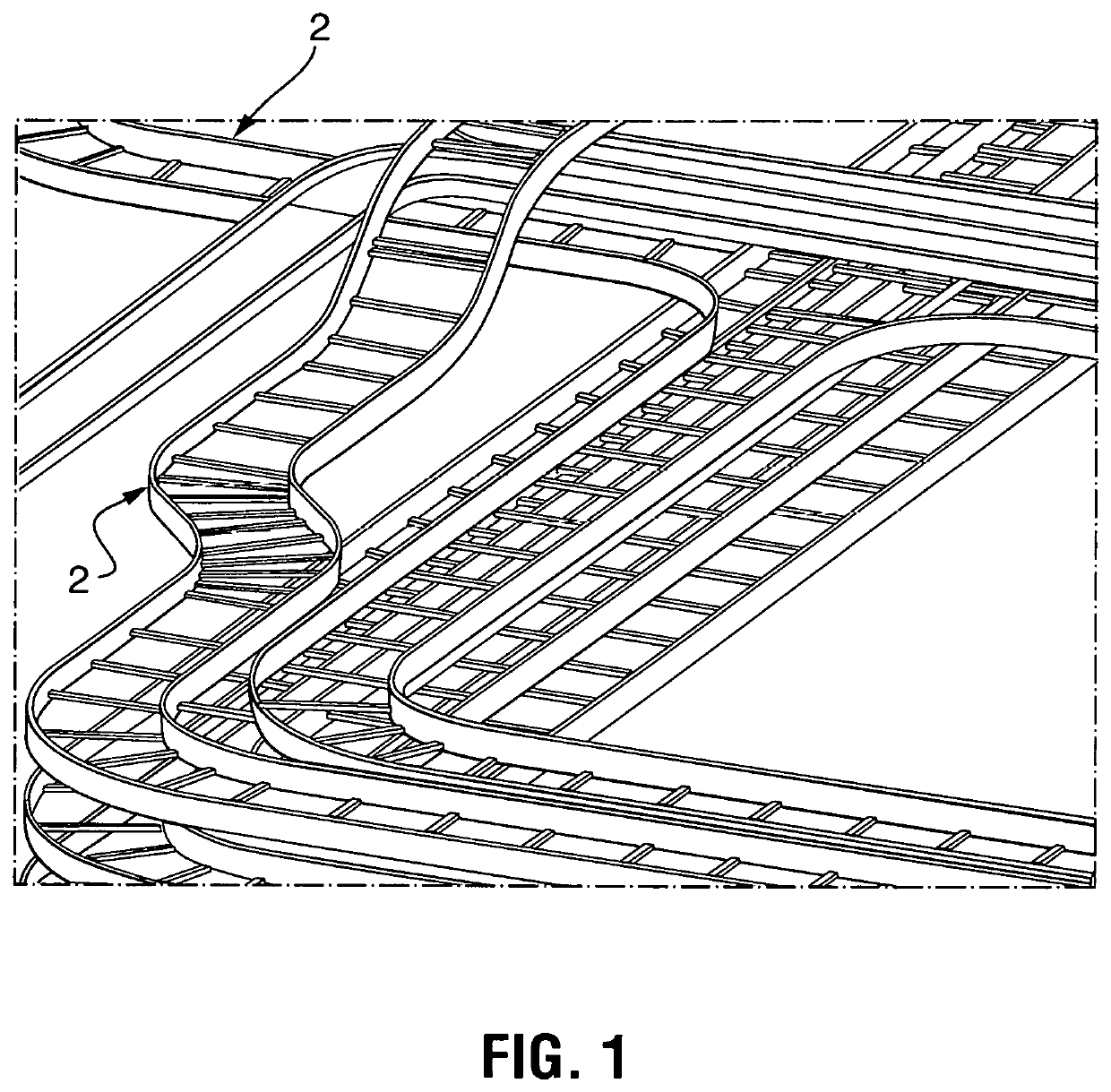
All of the different cable tray configurations winding through walls, around equipment and air handling system and so forth, often times prove very difficult to install cabling due to the fact that the installers cannot stand over or near the cable try to help guide and install the cabling or to even install a pull string or rope which may then be used to pull heavier cables into the tray.

Method used


Image

  • Cable pulling apparatus for cable tray
  • Cable pulling apparatus for cable tray
  • Cable pulling apparatus for cable tray

Examples


Embodiment Construction

[0054]The terminology used herein is for the purpose of describing particular example embodiments only and is not intended to be limiting. As used herein, the singular forms “a,”“an,” and “the” may be intended to include the plural forms as well, unless the context clearly indicates otherwise. The terms “comprises,”“comprising,”“including,” and “having,” are inclusive and therefore specify the presence of stated features, integers, steps, operations, elements, and / or components, but do not preclude the presence or addition of one or more other features, integers, steps, operations, elements, components, and / or groups thereof. The method steps, processes, and operations described herein are not to be construed as necessarily requiring their performance in the particular order discussed or illustrated, unless specifically identified as an order of performance. It is also to be understood that additional or alternative steps may be employed.

[0055]When an element or layer is referred to...


PUM


Abstract

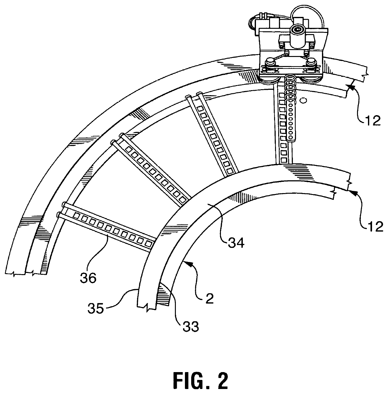
A device for pulling a cable down the length of a cable tray including a trolley with rollers which rollingly grasp the upper side portion of the cable tray and allow the trolley to roll along the tray. The trolley includes a swivel cord grip which is releasably attached to one end of the cable, thus allowing the cable puller to pull the cable along the cable tray as the cable puller is propelled along the cable tray. The trolley can be pulled along manually by using one of two pull lines or ‘jet lines’ which are attached to the cable puller and lead to each end of the cable tray, or, more preferably, the trolley can be propelled up or down the cable tray by a remotely controlled motor which drives one or more of the rollers.

Description

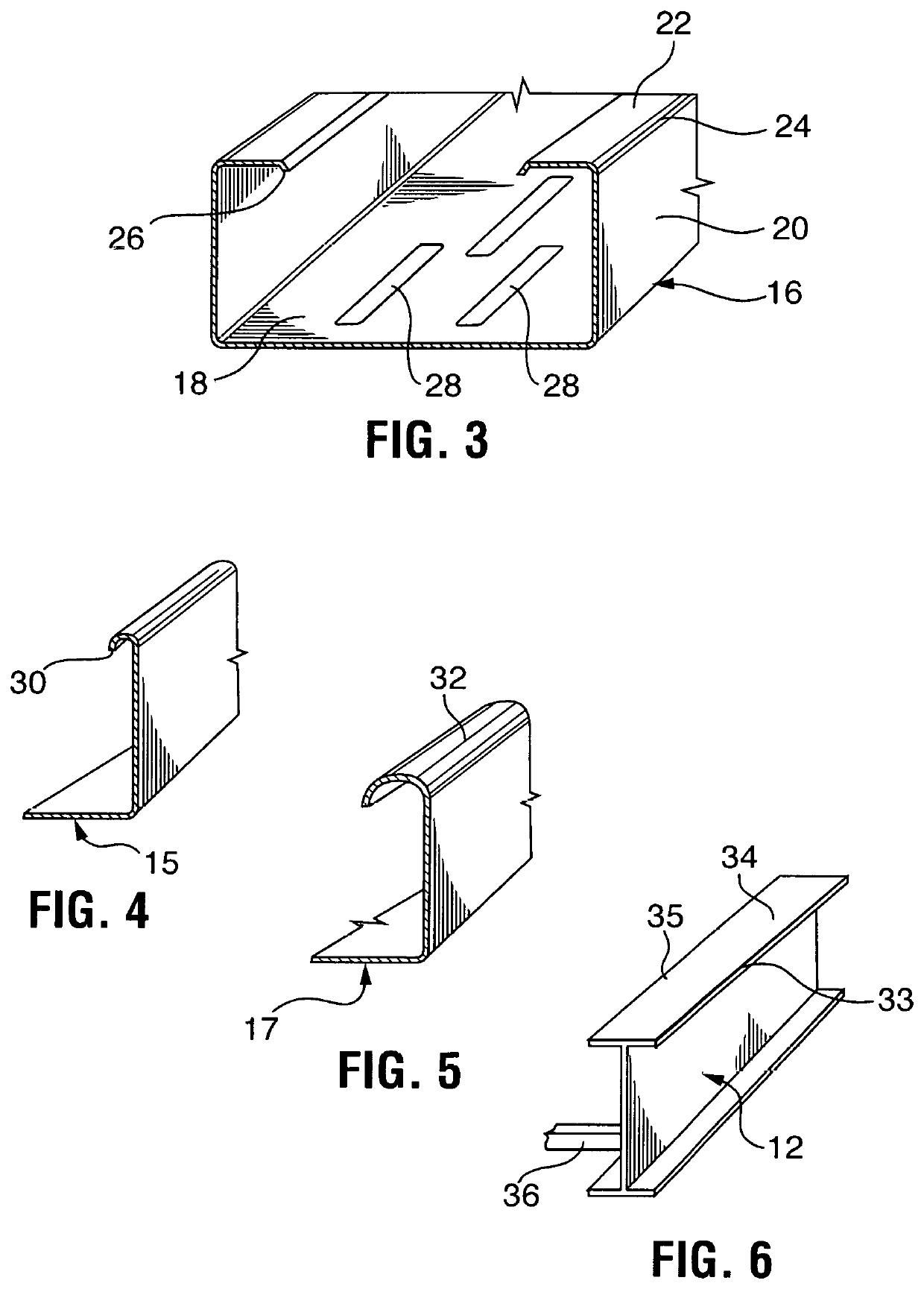
CROSS REFERENCES TO RELATED APPLICATIONS[0001]This application claims priority from U.S. Provisional Application Ser. No. 62 / 525,542 filed on Jun. 27, 2017 which is incorporated by reference herein in its entirety.TECHNICAL FIELD[0002]The present invention relates to the field of devices used to pull rope or cable into a cable tray.BACKGROUND OF THE INVENTION[0003]When wiring buildings, a cable tray system can used to support insulated electric cables used for power distribution and communication. Cable trays are used as an alternative to open wiring or electrical conduit systems wherein galvanized pipping is installed first and then the wiring is pulled through the piping. Installation of such piping and wiring is hard, time consuming work and can make repair and troubleshooting very difficult. Cable trays are especially useful in situations where changes to a wiring system are anticipated, since new cables can be installed by laying them in the tray, instead of pulling them throug...

Claims


Application Information

Patent Timeline
Patent Type & Authority Patents(United States)
IPC IPC(8): H02G1/08H02G3/04
CPCH02G1/081H02G1/088H02G3/0456
Inventor KING, DANIEL SCOTTSHEETS, CHARLES A
Owner SHEETS CHARLES A
Learn More