Error correction device and optical transmission/reception device

a technology of error correction and optical transmission, applied in error correction/detection using ldpc codes, electromagnetic transceivers, coding, etc., can solve the problems of delay, expansion of decoding circuit, and limitation of the number of error bits that can be corrected

Active Publication Date: 2021-09-28
MITSUBISHI ELECTRIC CORP
View PDF9 Cites 0 Cited by
  • Summary
  • Abstract
  • Description
  • Claims
  • Application Information

AI Technical Summary

Benefits of technology

[0024]According to the optical transmission / reception device of the present invention, the window size and the decoding iteration count are configured to be variable depending on the throughput input to the error correction decoding unit. With this configuration, it is possible to perform the multi-level encoding capable of handling various throughputs without changing a circuit configuration.

Problems solved by technology

However, there is a limitation on the number of error bits that can be corrected.
However, while the spatially-coupled LDPC code is expected to exhibit improvement in its performance as the combined code length becomes larger, the spatially-coupled LDPC code causes expansion of a decoding circuit and delay.

Method used


Image

  • Error correction device and optical transmission/reception device
  • Error correction device and optical transmission/reception device
  • Error correction device and optical transmission/reception device

Examples


first embodiment

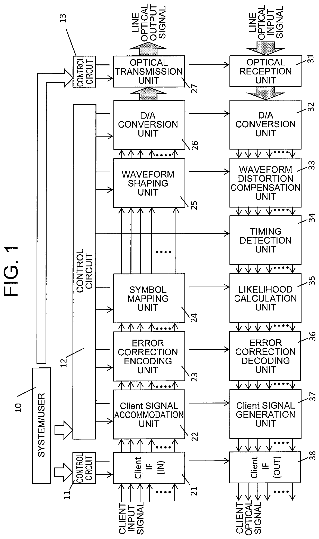
[0041]FIG. 1 is a block diagram for illustrating a configuration of an optical transmission / reception device according to a first embodiment of the present invention.

[0042]The optical transmission / reception device includes an error correction encoding device, which includes an error correction encoding unit 23, and an error correction decoding device, which includes an error correction decoding unit 36.

[0043]The error correction encoding unit 23 encodes a sequence to be transmitted, which is to be transmitted by the optical transmission / reception device, with an LDPC code. Further, the error correction decoding unit 36 decodes a received sequence received by the optical transmission / reception device, which has been encoded with an LDPC code.

[0044]Now, the configuration of the optical transmission / reception device is described.

[0045]In FIG. 1, a client IF (IN) 21 is an input interface circuit, to which a client signal is to be input. A client input signal is input to the client IF (I...

second embodiment

[0133]In a second embodiment of the present invention, another configuration of the error correction decoding unit 36 is described with reference to FIG. 12. The second embodiment differs from the first embodiment only in the configuration of the error correction decoding unit 36, and other configurations and operations of the second embodiment are the same as those of the first embodiment. A description thereof is therefore omitted here.

[0134]In the first embodiment described above, as illustrated in FIG. 5, the LDPC convolutional code decoding operation circuit 3622 provided in the error correction decoding unit 36 is constructed by one large arithmetic core circuit. When the LDPC convolutional code decoding operation circuit 3622 is constructed by one large arithmetic core circuit in this manner, the complexity of the circuit increases. When the window size win and the decoding iteration count itr can be freely set, estimation of the scale of the decoding processing circuit becom...

third embodiment

[0141]In the first embodiment and the second embodiment, there has been described the configuration in which, in the decoding operation processing for the LDPC convolutional code, the window size and the decoding iteration count are controlled to be set for each bit or bit group in the multi-level encoding. However, the present invention is not limited to the LDPC convolutional code. For example, in decoding operation processing for an LDPC block code, the decoding iteration count itr may be controlled to be set for each bit or bit group in the multi-level encoding. Even with this configuration, it is possible to obtain a similar effect.


PUM


Abstract

Provided is an optical transmission / reception device including: an error correction encoding unit configured to encode a sequence to be transmitted with one type of LDPC code; and an error correction decoding unit configured to decode a received sequence encoded with the LDPC code. The error correction decoding unit performs decoding processing for the received sequence based on a check matrix of an LDPC convolutional code. The decoding processing is windowed decoding processing, which is performed by using a window extending over one or more check submatrices. A window size of the window and a decoding iteration count are configured to be variable, and the window size and the decoding iteration count are input from a control circuit connected to the error correction decoding unit.

Description

TECHNICAL FIELD[0001]The present invention relates to an error correction device and an optical transmission / reception device, and more particularly, to an error correction device and an optical transmission / reception device, which are configured to support multi-level encoding.BACKGROUND ART[0002]In general, an optical transmission system of recent years employs an error correction code as an effective method for achieving a high transmission capacity and long-distance transmission. The error correction code is a technology used in, for example, a wired / wireless communication system and a storage device. The error correction code is a technology for adding a redundant bit to digital data to be transmitted on a transmission side, to thereby enable correction of an error (bit) that has occurred in received data.[0003]As error correction encoding / decoding methods, various kinds of methods are proposed, such as Hamming codes, Bose-Chaudhuri-Hocquenghem (BCH) codes, and Reed-Solomon (RS...

Claims


Application Information

Patent Timeline
Patent Type & Authority Patents(United States)
IPC IPC(8): H03M13/00H03M13/11H04B10/40
CPCH03M13/1105H03M13/1154H03M13/616H04B10/40H03M13/1111H03M13/3707H03M13/3715H03M13/3723H03M13/116H03M13/255H03M13/356
Inventor KUBO, KAZUO
Owner MITSUBISHI ELECTRIC CORP
Why Eureka
Try Eureka