Light emitting device and lighting fixture provided with the same
a technology of light emitting devices and lighting fixtures, which is applied in the direction of solid-state devices, chemistry apparatuses and processes, and light compositions. it can solve the problems of eye fatigue, glare, and eye fatigue, and achieve excellent visual work and reduce eye fatigue. the effect of fatigu
- Summary
- Abstract
- Description
- Claims
- Application Information
AI Technical Summary
Benefits of technology
Problems solved by technology
Method used
Image
Examples
example 1
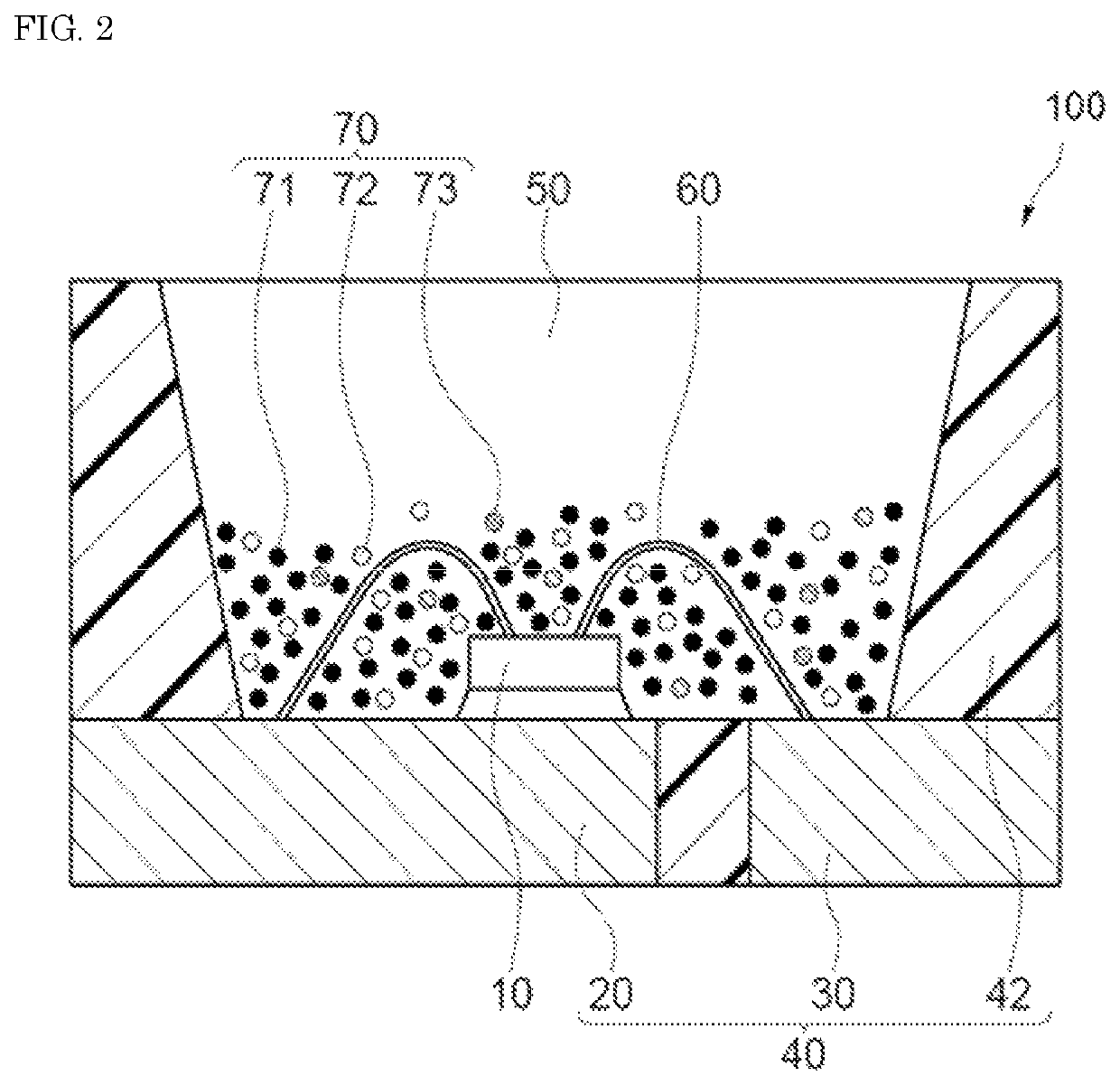
[0130]The fluorescent material 70 in which the first fluorescent material 71, the second fluorescent material 72, and the third fluorescent material 73 were blended such that the chromaticity coordinate in CIE1931 was located in the vicinity of X=0.312 and Y=0.328, and a silicone resin were mixed and dispersed, and the dispersion was then degassed to obtain a resin composition for fluorescent member. The fluorescent material total amount in the resin composition for fluorescent member was 68.6% by mass based on 100% by mass of the resin. In addition, the content MP1 of SAE that is the first fluorescent material 71 was 43.7% by mass, the content MP2 of LAG3 that is the second fluorescent material 72 was 45.8% by mass, and the content MP3 of SCASN1 that is the third fluorescent material 73 was 10.5% by mass relative to the fluorescent material total amount. Next, the molded article 40 having a convex as shown in FIG. 2 was prepared; the light emitting element 10 having a light emissio...
examples 2 to 5
, and 23, and Comparative Examples 1, 2 and 11
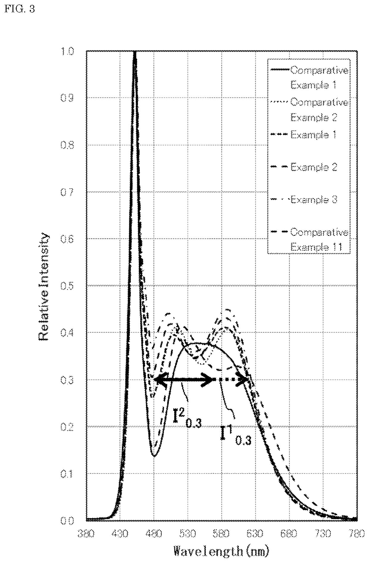
[0131]Light emitting devices were fabricated in the same manner as in Example 1, except for changing the kinds of the first fluorescent material 71, the second fluorescent material 72, and the third fluorescent material 73 and the content of each of the fluorescent materials relative to the fluorescent material total amount as shown in the following Table 3.
[0132]
TABLE 3Fluorescent material content (% by mass)FirstSecondThirdContentFluorescent materialfluorescentfluorescentfluorescentrelative toFirstSecondmaterialmaterialmaterialresinfluorescentfluorescentThird fluorescentMP1MP2MP3(% by mass)materialmaterialmaterialComparative14.583.22.348.2SAEYAG1 / LAG3SCASN3 / SCASN4Example 1(70 / 30)(50 / 50)Comparative71.818.49.969.7SAEYAG1SCASN1Example 2Example 143.745.810.568.6SAELAG3SCASN1Example 237.253.29.580.6SAELAG5SCASN1Example 336.154.29.783.1SAEGLAG6SCASN1Example 424.366.19.682.3SAEGLAG6SCASN1Example 513.177.39.676.3SAEGLAG6SCASN1Example 2324.073....
examples 6 to 10
, and 24, and Comparative Examples 3, 4 and 12
[0133]Light emitting devices were fabricated in the same manner as in Example 1, except for blending the first fluorescent material 71, the second fluorescent material 72, and the third fluorescent material 73 such that the chromaticity coordinate in CIE1931 was located in the vicinity of X=0.345 and Y=0.355; and changing the kinds of the first fluorescent material 71, the second fluorescent material 72, and the third fluorescent material 73 and the content of each of the fluorescent materials relative to the fluorescent material total amount as shown in the following Table 4. The aforementioned chromaticity coordinate is about 5,000K in terms of the correlated color temperature of the light emitting device and is corresponding to a range where the correlated color temperature is 4,500K or higher and lower than 5,700K.
[0134]
TABLE 4Fluorescent material content (% by mass)FirstSecondThirdContentFluorescent materialfluorescentfluorescentflu...
PUM
| Property | Measurement | Unit |
|---|---|---|
| light emission peak wavelength | aaaaa | aaaaa |
| light emission peak wavelength | aaaaa | aaaaa |
| light emission peak wavelength | aaaaa | aaaaa |
Abstract
Description
Claims
Application Information
 - R&D
- Intellectual Property
- Life Sciences
- Materials
- Tech Scout
- Unparalleled Data Quality
- Higher Quality Content
- 60% Fewer Hallucinations
Browse by: Latest US Patents, China's latest patents, Technical Efficacy Thesaurus, Application Domain, Technology Topic, Popular Technical Reports.
© 2025 PatSnap. All rights reserved.Legal|Privacy policy|Modern Slavery Act Transparency Statement|Sitemap|About US| Contact US: help@patsnap.com


