
Air ceiling inlet unit

a ceiling and air technology, applied in the direction of ducting arrangements, lighting and heating apparatuses, heating types, etc., can solve the problems of increasing heating costs, adversely affecting the health and production efficiency of live animals being housed, and most likely not uniform in air distribution or temperature, so as to increase the maximum airflow, increase the effect of air movement, and effective mixing

Active Publication Date: 2021-09-28
DOUBLE L GRP LLC
View PDF7 Cites 2 Cited by
  • Summary
  • Abstract
  • Description
  • Claims
  • Application Information

AI Technical Summary

Benefits of technology

The ceiling invention provides better air mixing at different openings, solves leakage issues, and increases maximum airflow while still giving control of air movement at smaller openings. It has a housing that can be mounted on the interior ceiling of a building, two deeper curved blades, and a hinge design that reduces air leakage. It is fully insulated and designed to always roll away from problem areas. The blades are curved and designed for optimal air jet throw and mixing uniformity. The design minimizes cross-sectional area during minimum ventilation periods and maximizes air jet throw and inlet efficiency. It increases ventilation performance while reducing energy usage.

Problems solved by technology

If proper ventilation is not achieved during the winter, buildings will most likely be cool, damp, and non-uniform in air distribution or temperature if the building is located in the northern climates.
An ongoing problem in such buildings is to maintain a proper interior temperature and air uniformity especially where the building houses livestock or swine.
Excessive heat or cold in the building can adversely affect the health and production efficiencies of the live animals being housed.
Leakage of outside air into the interior room from the attic increases heating costs during cold exterior temperatures, since more fuel is required to maintain a desired condition.
During times of extreme high temperatures outside the building, leakage of attic air to the interior room of the building can potentially add to heat stress for the swine or livestock and add cost due to an increased ventilation rate to mitigate the rise in temperature.
However, with known ceiling inlets of the actuated type with two blades, the air jet throw during minimum ventilation is not the most efficient, thus reducing the uniformity of mixing of air quality and temperature in all areas of the interior room.
Also, for inlets that have tolerable air jet throw, the maximum volumetric flow rate of air (in cfm) is not high enough to satisfy ventilation rates needed by exhaust fans without addition of quantities of said inlets into room.

Method used


Image

  • Air ceiling inlet unit
  • Air ceiling inlet unit
  • Air ceiling inlet unit

Examples


Embodiment Construction

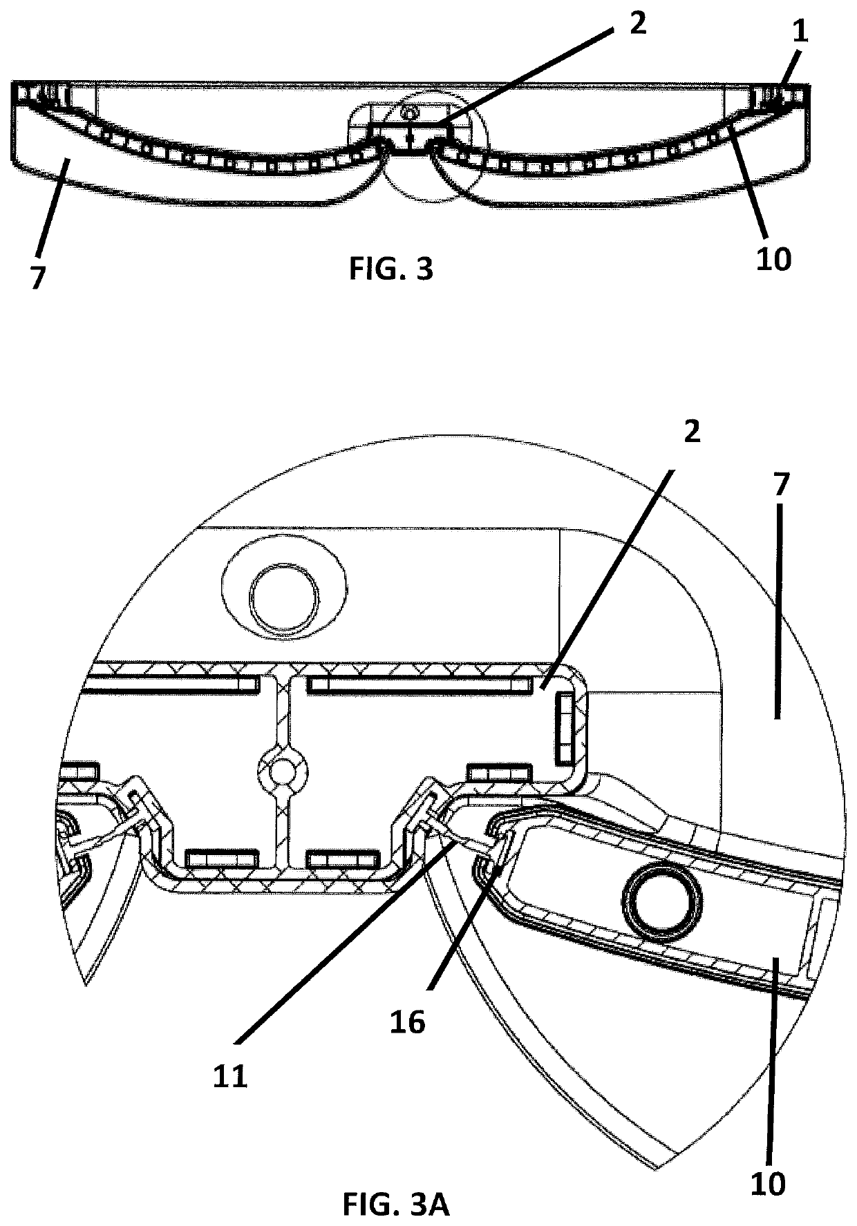
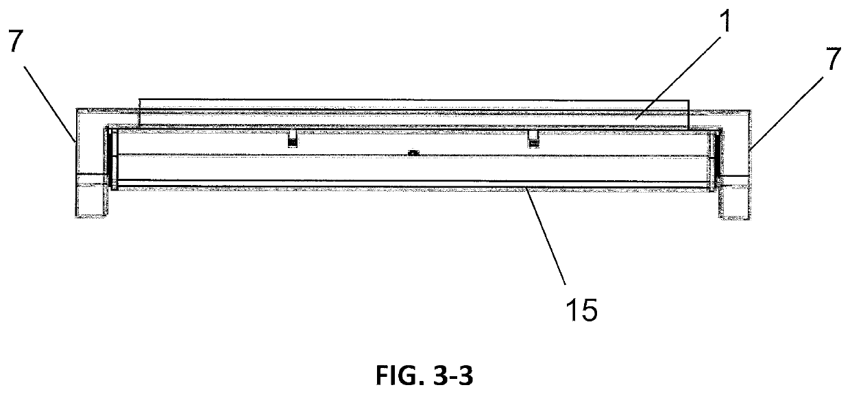
[0041]Referring first to FIGS. 1 and 2, the basic ceiling inlet unit of the invention is comprised of a frame having two endcap sub-assemblies 4 that connect the frame members and the center profile member 2 and hold them together so that the frame 1 can be used to install the ceiling inlet unit of the invention in an opening in the ceiling of an interior room of a building to be ventilated. As is well known to those skilled in the art, the ceiling inlet unit is combined with an actuator and exhaust or positive pressure fan, outlet damper, or shutter wall (not shown) which, when on and the actuator opens the ceiling inlet unit of the invention, will draw air from the attic of the building through the ceiling inlet unit, and will bring air into the interior room of the building. FIG. 1 shows the top face of the unit at it would appear when viewed from inside of the building before installation, and FIG. 2 shows the top face which faces the rough opening in the ceiling. The frame prov...


PUM


Abstract

A ceiling inlet unit that assists in bringing air into the interior room of a building. The unit has a housing providing an opening to the attic of the building, the housing having movable blades with brush borders on the ends, pivotally mounted with a continuous hinge in the housing with seals to minimize air leakage when the blades are closed. The housing is designed in such a way to provide optimal air mixing situations through available cross-sectional area at different ventilation stages. The blades are designed to maximize air jet throw during lower ventilation stages, and provide superior total airflow during maximum ventilation stages.

Description

[0001]This application claims priority to U.S. Provisional Patent Application No. 62 / 794,876 filed Jan. 21, 2019, which application is incorporated by reference herein.BACKGROUND OF THE INVENTION[0002]Ventilating the interior of buildings is highly desirable and essential wherever living creatures or plants are being maintained. For example, the interior conditions must be controlled in buildings used for warehousing or industrial storage, for the raising of vegetables and plants, or for raising swine or livestock. For those buildings where living creatures are being raised, proper interior ventilation is essential to their good health and in order to have good production efficiencies. If proper ventilation is not achieved during the winter, buildings will most likely be cool, damp, and non-uniform in air distribution or temperature if the building is located in the northern climates. In the summer, the interior of the building will likely be hot and humid. Ventilation is a process ...

Claims


Application Information

Patent Timeline
Patent Type & Authority Patents(United States)
IPC IPC(8): F24F13/14A01K1/00
CPCF24F13/1413A01K1/0052A01K1/0058F24F13/1406F24F13/06F24F2221/14
Inventor TABOR, ELIZABETHSTREICHER, DICK
Owner DOUBLE L GRP LLC
Learn More