
Feeding a coil for magnetic resonance imaging

a magnetic resonance imaging and body coil technology, applied in the field of feeding a body coil for magnetic resonance imaging, can solve the problems of more or less complicated matching control circuitry, need for tuning high-power reactances, etc., and achieve the effect of convenient and efficien

Active Publication Date: 2021-08-24
KONINKLJIJKE PHILIPS NV
View PDF34 Cites 0 Cited by
  • Summary
  • Abstract
  • Description
  • Claims
  • Application Information

AI Technical Summary

Benefits of technology

This approach enhances power efficiency by minimizing power reflection across a wider range of loads, enabling better MRI measurements by dynamically adjusting to different examination object weights, thus improving the overall performance of the MRI system.

Problems solved by technology

However, these methods suffer from a more or less complicated matching control circuitry and the need for tuneable high power reactances placed at or very close to the body coil.

Method used


Image

  • Feeding a coil for magnetic resonance imaging
  • Feeding a coil for magnetic resonance imaging

Examples


Embodiment Construction

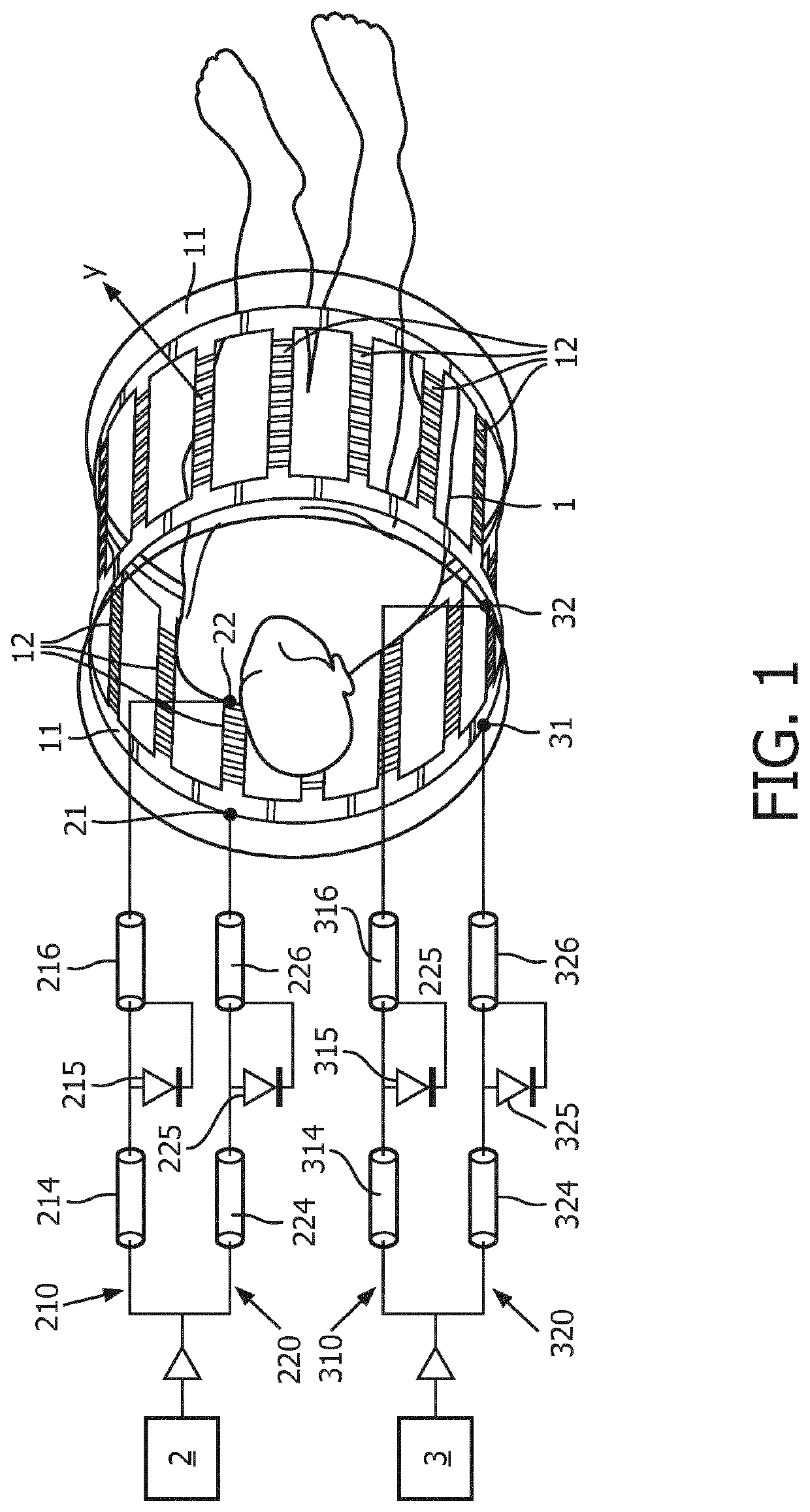
[0051]FIG. 1 depicts a system comprising a body coil 9 for magnetic resonance imaging and two RF amplifiers 2, 3 connected to the body coil 9 for feeding the body coil 9 with two different RF signals, The body coil 9 comprises two different ports 21, 22, and 31, 32 for each RF amplifier 2, 3, respectively, for feeding a respective RF signal into the body coil 9. Further, the body coil 9 is provided with two switches for selectively activating only one single port 21 or 22 for the first RF amplifier 2 and 31 or 32 and the second amplifier 3, respectively, for feeding the RF signal to the body coil 9 at a time.

[0052]These switches are comprised of two separate lines 210, 220, 310, 320 leading from the RF amplifiers 2, 3 to the different ports 21, 22, 31, 32, respectively. Each line 210, 220, 310, 320 comprises a switching diode 215, 225, 315, 325 for opening or closing the connection of the RF amplifier 2, 3 with the body coil 9, respectively. The switching diodes 215, 225, 315, 325 a...


PUM


Abstract

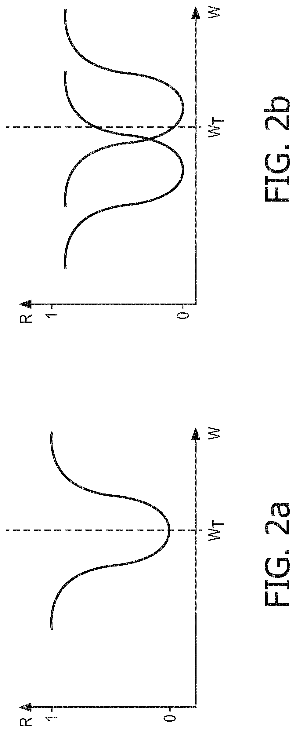
The present invention is directed to a system comprising a body coil (9) for magnetic resonance imaging and an RF amplifier connected to the body coil (9) for feeding the body coil (9) with an RF signal, wherein the body coil (9) comprises two different ports (21, 22) for feeding the RF signal into the body coil (9), the body coil (9) is provided with a switch for selectively activating only one single port (21, 22) for feeding the RF signal to the body coil (9) at a time, and the two ports (21, 22) are located at different locations of the body coil (9) such that the dependence of the reflected part of the RF signal fed into the body coil (9) from the weight of the examination object (1) to which the body coil (9) is applied is different for the two ports (21, 22). In this way, a possibility for adapting a MRI measurement to different load situations due to different weights of an examination object (1) in an easy and efficient way is provided, thereby providing the possibility for impedance matching of the body coil by selecting the appropriate driven port.

Description

CROSS REFERENCE TO RELATED APPLICATIONS[0001]This application is a U.S. national phase application of International Application No. PCT / EP2018 / 076059 filed on Sep. 26, 2018, which claims the benefit of EP Application Serial No. 17196064.4 filed on Oct. 12, 2017 and is incorporated herein by reference.FIELD OF THE INVENTION[0002]The invention relates to the field of feeding a body coil for magnetic resonance imaging (MRI), and in particular to a system comprising a body coil for magnetic resonance imaging and an RF amplifier connected to the body coil for feeding the body coil with an RF signal is provided. The invention further relates to a method for feeding a body coil of a magnetic resonance imaging system with an RF signal by an RF amplifier.BACKGROUND OF THE INVENTION[0003]As is generally known in the art, in an MRI system, an examination object, usually a examination object, is exposed to a uniform main magnetic field (B0 field) so that the magnetic moments of the nuclei withi...

Claims


Application Information

Patent Timeline
Patent Type & Authority Patents(United States)
IPC IPC(8): G01R33/34A61B5/055G01R33/36
CPCG01R33/34092A61B5/055G01R33/3614G01R33/3621G01R33/3664G01R33/34076G01R33/3628
Inventor VERNICKEL, PETERLEUSSLER, CHRISTOPHSCHMALE, INGOFINDEKLEE, CHRISTIANLIPS, OLIVER
Owner KONINKLJIJKE PHILIPS NV
Learn More