Method for producing armature, method for producing dynamo-electric machine, armature, dynamo-electric machine, and device for producing armature

a technology of dynamo-electric machines and armatures, which is applied in the direction of dynamo-electric machines, electrical apparatus, magnetic circuit shapes/forms/construction, etc., can solve the problems of reducing the efficiency of rotary electric machines, difficult to narrow the slot opening width, and coil interference with the core, etc., to achieve excellent productivity, low cost, and high efficiency

Active Publication Date: 2021-08-10
MITSUBISHI ELECTRIC CORP
View PDF19 Cites 2 Cited by
  • Summary
  • Abstract
  • Description
  • Claims
  • Application Information

AI Technical Summary

Benefits of technology

[0016]The armature producing method and the rotary electric machine producing device according to the present invention can provide an armature and a rotary electric machine that have a narrowed slot opening width and that are downsized, highly efficient, low in cost, and excellent in productivity.
[0017]The armature and the rotary electric machine according to the present invention have the circumferential-direction protrusion portions at the ends of the tooth portions. Thus, magnetic resistance between the rotor and the armature is reduced, whereby rotor iron loss can be reduced. In addition, the coil space factor can be increased, and thus a rotary electric machine having high efficiency and high output can be obtained.
[0018]The armature producing device according to the present invention can produce an armature for a rotary electric machine having high efficiency and high output, with use of simple equipment and with excellent productivity.

Problems solved by technology

However, in this type of armature, if the slot opening width of the armature is narrowed, the coils interfere with the core.
Therefore, it is difficult to narrow the slot opening width.
If the slot opening width is expanded, there is a problem that magnetic resistance increases, efficiency of the rotary electric machine reduces, and the size of the rotary electric machine increases.
In addition, if the slot opening width is expanded, it is impossible to mechanically prevent the coils from protruding toward the inner circumferential side, so that it is necessary to fix the coils by fixation means such as adhesion.

Method used


Image

  • Method for producing armature, method for producing dynamo-electric machine, armature, dynamo-electric machine, and device for producing armature
  • Method for producing armature, method for producing dynamo-electric machine, armature, dynamo-electric machine, and device for producing armature
  • Method for producing armature, method for producing dynamo-electric machine, armature, dynamo-electric machine, and device for producing armature

Examples


embodiment 1

[0079]Hereinafter, embodiment 1 of the present invention will be described with reference to the drawings.

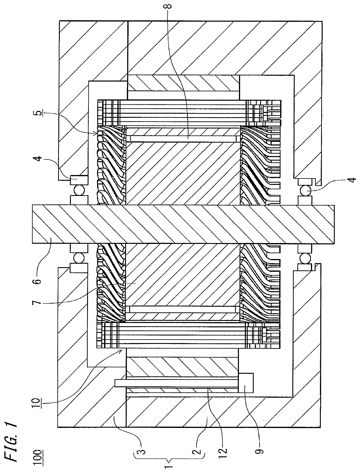
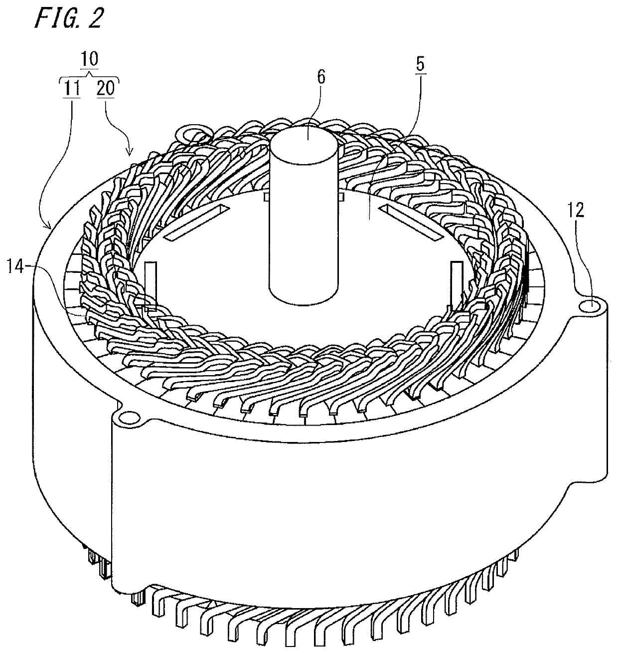
[0080]FIG. 1 is a sectional view showing a rotary electric machine according to embodiment 1 of the present invention, and FIG. 2 is a perspective view showing an armature of the rotary electric machine shown in FIG. 1. In the following description, a rotary shaft direction (vertical direction in FIG. 1) is defined as an axial direction, a rotary shaft center direction (horizontal direction in FIG. 1) is defined as a radial direction, and a rotational direction about the rotary shaft is defined as a circumferential direction.

[0081]In the drawings, a rotary electric machine 100 includes: a housing 1 having a bottomed cylindrical frame 2 and a bracket 3 closing an opening of the frame 2; an armature 10 fastened to the bracket 3 with bolts 9 through attachment holes 12; a rotary shaft 6 rotatably supported to a bottom portion of the frame 2 and the bracket 3 via bearings 4; and a r...

embodiment 2

[0200]Next, embodiment 2 of the present invention will be described with reference to FIG. 43 to FIG. 45. In embodiment 2, only points different from embodiment 1 will be described.

[0201]FIG. 43 shows the armature after the outer core is inserted in embodiment 2 of the present invention, and is a plan sectional view corresponding to FIG. 16 in embodiment 1. FIG. 44 is a detailed sectional view of part J of the armature shown in FIG. 43, and corresponds to FIG. 17 in embodiment 1. FIG. 45 is a schematic view illustrating a core insertion step according to embodiment 2 of the present invention, and corresponds to FIG. 19 in embodiment 1.

[0202]As shown in FIG. 43, inner cores 1030 are arranged on the inner circumferential side of an outer core 1040. As shown in FIG. 44, fitting portions 1132 of the inner cores 1030 are fitted and fixed to grooves 1050 of the outer core 1040. At this time, a circumferential-direction width Y4 of a circumferential-direction protrusion 1131 at the end of ...


PUM


Abstract

This method includes: a coil assembly step of combining a plurality of coil units to form a coil basket; a core insertion step of inserting inner cores of in the radial direction to the coil basket; and a fixation member insertion step of inserting a fixation member to the outer circumference of the inner core. In the core insertion step, the radial-direction position of the coil basket is retained at a core insertion time position shifted outward in the radial direction relative to a normal position after armature completion, and the inner cores are inserted in the radial direction to the coil basket. After the core insertion step, the radial-direction positions of the coil basket and the inner cores are moved inward in the radial direction to the normal position after armature completion.

Description

TECHNICAL FIELD[0001]The present invention relates to an armature producing method, a rotary electric machine producing method, an armature, a rotary electric machine, and an armature producing device, and in particular, relates to an armature producing method, a rotary electric machine producing method, an armature, a rotary electric machine, and an armature producing device that enable the slot opening width to be narrowed.BACKGROUND ART[0002]In recent years, rotary electric machines such as an electric motor and an electric generator have been required to be downsized and have higher outputs. As means for solving the requirements, it is known that an armature of distributed winding type in which the space factor of coils is increased using rectangular conductive wires is used. Coils that have been shaped in advance are combined to form a coil basket, and a core is inserted into the coil basket, thereby obtaining effects of decreasing welded parts of the coils and improving produc...

Claims


Application Information

Patent Timeline
Patent Type & Authority Patents(United States)
IPC IPC(8): H02K15/02H02K3/48H02K15/085H02K1/16H02K1/18
CPCH02K15/026H02K1/16H02K1/165H02K1/18H02K1/185H02K3/48H02K15/02H02K15/085H02K15/022H02K1/148H02K15/12
Inventor HINO, TATSUROIKEUCHI, YUICHIROEGASHIRA, KOHEIYOKOGAWA, TETSUYANAKAMURA, MASASHIINOUE, MASAYA
Owner MITSUBISHI ELECTRIC CORP
Why Eureka
Try Eureka