Energy generation system using biomass and method of controlling the same
a technology of energy generation system and energy generation system, which is applied in the direction of electrochemical generators, sustainable manufacturing/processing, instruments, etc., can solve the problems of insufficient consideration of the effect of the flow of biomass to the generation of energy and the supply of generated energy
- Summary
- Abstract
- Description
- Claims
- Application Information
AI Technical Summary
Benefits of technology
Problems solved by technology
Method used
Image
Examples
first embodiment
A. First Embodiment
[0012](A-1) Entire Configuration of System:
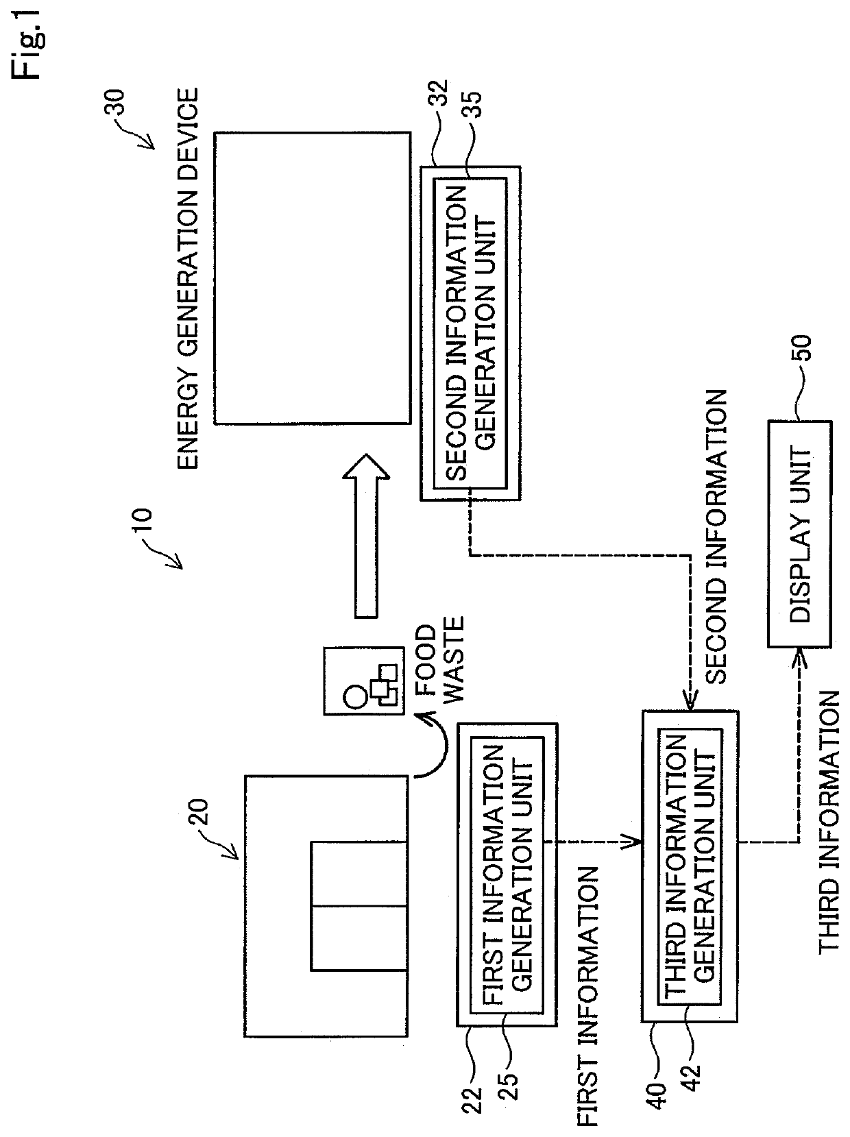
[0013]FIG. 1 is an explanatory diagram illustrating a schematic configuration of an energy generation system 10 as a first embodiment of the disclosure. The energy generation system 10 of the first embodiment is a system for generating energy using biomass. The energy generation system 10 includes a distributor 20, an energy generation device 30, a first controller 22, a second controller 32, a third controller 40, and a display unit 50.
[0014]The distributor 20 is a distributor handling food where food waste occurs. The distributor 20 may be a food retailer such as a convenience store and a supermarket, a restaurant, a hotel, a hospital, or a composite facility including a plurality of them, for example.
[0015]The energy generation device 30 is a device that generates at least one of energy and energy sources (hereinafter, energy and energy sources are also referred to collectively as energy and the like) using food waste ...
second embodiment
B. Second Embodiment
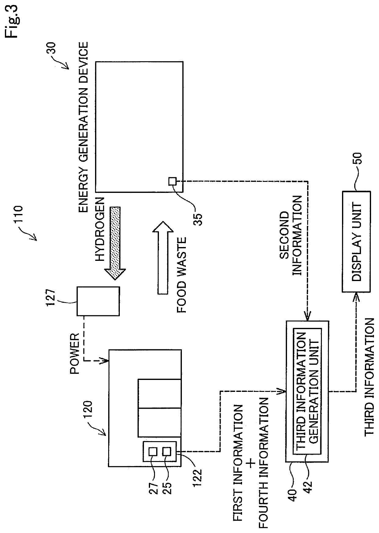
[0034]FIG. 3 is an explanatory diagram illustrating a schematic configuration of an energy generation system 110 as a second embodiment of the disclosure. In the energy generation system 110 of the second embodiment, the parts same as the energy generation system 10 of the first embodiment are represented with the same referential symbols, and the detailed description thereof is omitted.
[0035]In the energy generation system 110 of the second embodiment, the distributor 120 uses energy and the like generated by the energy generation device 30 using biomass disposed of by the distributor 120. To be more specific, the distributor 120 has a fuel cell 127 that is a power generation device generating power using hydrogen and oxygen. Then, the distributor 120 receives supply of hydrogen that is energy sources, as energy and the like generated by the energy generation device 30, so that the fuel cell 127 generates power using the hydrogen, thus covering at least apart of...
third embodiment
C. Third Embodiment
[0040]FIG. 4 is an explanatory diagram illustrating a schematic configuration of an energy generation system 210 as a third embodiment of the disclosure. In the energy generation system 210 of the third embodiment, the parts same as the energy generation system 10 of the first embodiment are represented with the same referential symbols, and the detailed description thereof is omitted.
[0041]In the energy generation system 210 of the third embodiment, a plurality of distributors 220a, 220b, 220c exist. In FIG. 4, the number of distributors is three. However, two or more distributors may exist. Each of the distributors 220a, 220b, 220c may have a plurality of facilities where biomass is disposed of. For example, each of the distributors 220a, 220b, 220c may be a collective of facilities such as a plurality of convenience stores belonging to a same group or a collective of facilities such as a plurality of retail stores run by a same management subject.
[0042]In the t...
PUM
| Property | Measurement | Unit |
|---|---|---|
| energy | aaaaa | aaaaa |
| power | aaaaa | aaaaa |
| generating energy | aaaaa | aaaaa |
Abstract
Description
Claims
Application Information
 - R&D
- Intellectual Property
- Life Sciences
- Materials
- Tech Scout
- Unparalleled Data Quality
- Higher Quality Content
- 60% Fewer Hallucinations
Browse by: Latest US Patents, China's latest patents, Technical Efficacy Thesaurus, Application Domain, Technology Topic, Popular Technical Reports.
© 2025 PatSnap. All rights reserved.Legal|Privacy policy|Modern Slavery Act Transparency Statement|Sitemap|About US| Contact US: help@patsnap.com


