
Display panel, manufacturing method thereof, and display module

a manufacturing method and display panel technology, applied in the field of display devices, can solve the problems of higher production costs and difficulty in producing rgb light-emitting units, and achieve the effect of improving the resolution of the display panel and simplifying the manufacturing method of the display panel

Active Publication Date: 2021-07-06
WUHAN CHINA STAR OPTOELECTRONICS SEMICON DISPLAY TECH CO LTD
View PDF17 Cites 0 Cited by
  • Summary
  • Abstract
  • Description
  • Claims
  • Application Information

AI Technical Summary

Benefits of technology

This patent application aims to simplify the manufacturing process of a display panel by using an auxiliary electrode and stacked light emitting layers. This eliminates the need for a fine metal mask plate, allowing for the emission of light of various colors from a single pixel and improving the overall resolution of the display panel.

Problems solved by technology

At present, people are increasingly demanding display quality, that is, the resolution, but there are still many challenges in manufacturing high-quality, high-resolution OLED displays.
However, this structure has extremely high requirements on the FMM, and especially in a process of manufacturing a large-sized panel, it is particularly difficult to produce the RGB light-emitting units by using the FMM to perform accurate evaporation.
Utilization of the FMM causes difficulty in a manufacturing process, and also leads to higher production costs.

Method used


Image

  • Display panel, manufacturing method thereof, and display module
  • Display panel, manufacturing method thereof, and display module
  • Display panel, manufacturing method thereof, and display module

Examples


Embodiment Construction

[0058]Embodiments of the present disclosure are described in detail with reference to the accompanying drawings as follows. Directional terms such as up / down, right / left and the like may be used for the purpose of enhancing a reader's understanding about the accompanying drawings, but are not intended to be limiting. Specifically, the terminologies in the embodiments of the present disclosure are merely for the purpose of describing certain embodiments, but not intended to limit the scope of the invention. The same reference numbers are used throughout the drawings to refer to the same or similar parts.

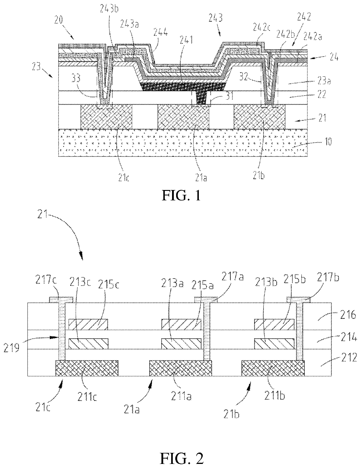
[0059]Please refer to FIG. 1. FIG. 1 is a schematic structural view illustrating a display panel according to one embodiment of the present invention.

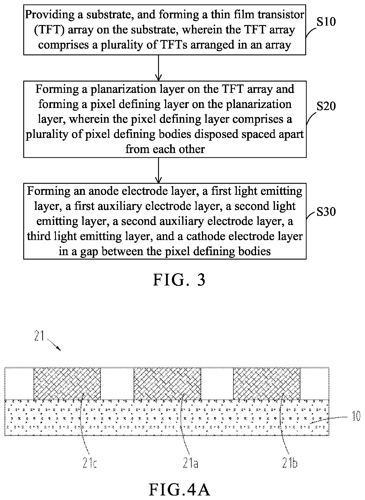
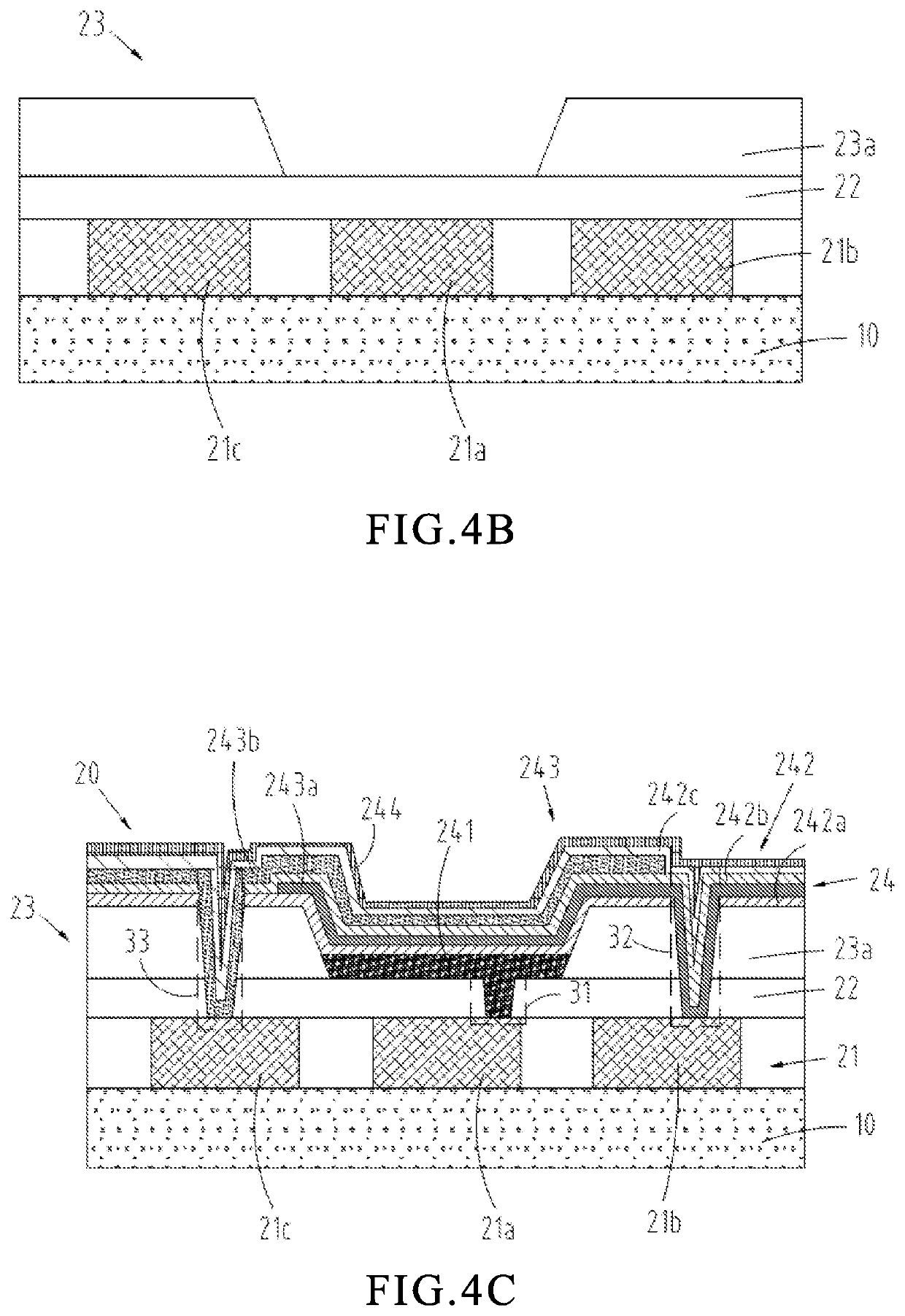
[0060]The present invention provides a display panel. The display panel comprises a substrate 10 and a pixel unit 20 disposed on a surface of the substrate 10. The pixel unit 20 comprises a thin film transistor (TFT) array 21, a planariz...


PUM

PropertyMeasurementUnit
areaaaaaaaaaaa
colorsaaaaaaaaaa
brightnessaaaaaaaaaa

Abstract

The present invention provides a display panel, a manufacturing method thereof, and a display module. The display panel includes a light emitting device. The light emitting device includes an anode electrode layer, a cathode electrode layer, and at least two light emitting layers, and at least one auxiliary electrode layer. The at least two light emitting layers are disposed between the anode electrode layer and the cathode electrode layer. Each auxiliary electrode layer is disposed between two adjacent light emitting layers. The at least one auxiliary electrode layer, the anode electrode layer, and the cathode electrode layer are separated from each other. The light emitting layers are separated from each other.

Description

FIELD OF DISCLOSURE[0001]The present invention relates to a field of display devices and in particular, to a display panel, a manufacturing method thereof, and a display module.DESCRIPTION OF RELATED ART[0002]In flat panel display technology, an organic light emitting diode (OLED) display has many advantages, such as being light and thin, active illumination, fast responses, wide viewing angles, a wide color range, high brightness, and low power consumption, so the OLED display is considered to be the third generation display technology after liquid crystal displays (LCDs). Compared with the LCDs, an OLED has the advantages of more power saving, being thinner, and wider viewing angles, which are unmatched by the LCDs. At present, people are increasingly demanding display quality, that is, the resolution, but there are still many challenges in manufacturing high-quality, high-resolution OLED displays.[0003]Currently, OLED screens in a display field usually use a structure in which R,...

Claims


Application Information

Patent Timeline
Patent Type & Authority Patents(United States)
IPC IPC(8): H01L27/32H01L51/50H01L51/52
CPCH01L27/3262H01L27/3246H01L51/5072H01L51/5206H01L51/5221H10K59/122H10K59/123H10K59/1213H10K59/80516H10K59/32H10K59/121H10K50/16H10K50/81H10K50/82
Inventor WU, JUNJIE
Owner WUHAN CHINA STAR OPTOELECTRONICS SEMICON DISPLAY TECH CO LTD
Learn More