
Weight plate and barbell component system

Active Publication Date: 2021-07-06
BAKER SCOTT BRADLEY
View PDF47 Cites 3 Cited by
  • Summary
  • Abstract
  • Description
  • Claims
  • Application Information

AI Technical Summary

Benefits of technology

The patent describes a system that saves time, reduces costs, improves safety, and helps to minimize liability for facilities. The system allows for easy attachment of weights to barbells without the need for clamps, which saves time and prevents damage to equipment. The system is designed to require users to engage a locking mechanism before attaching weights to barbells, providing increased safety. The features of the system may also result in cost savings for facilities and reduce liability.

Problems solved by technology

Many times at larger gym locations, there just are not enough clamps available and users may thus workout with these heavy weight plates without the required securing clamps.
This may obviously increase the amount of safety concerns by the user, and may also raise the level of liability for the facility.

Method used


Image

  • Weight plate and barbell component system
  • Weight plate and barbell component system
  • Weight plate and barbell component system

Examples


Embodiment Construction

[0038]Reference is now made to the accompanying drawings which show the features and different embodiments of a weight plate constructed and configured in accordance with the present invention.

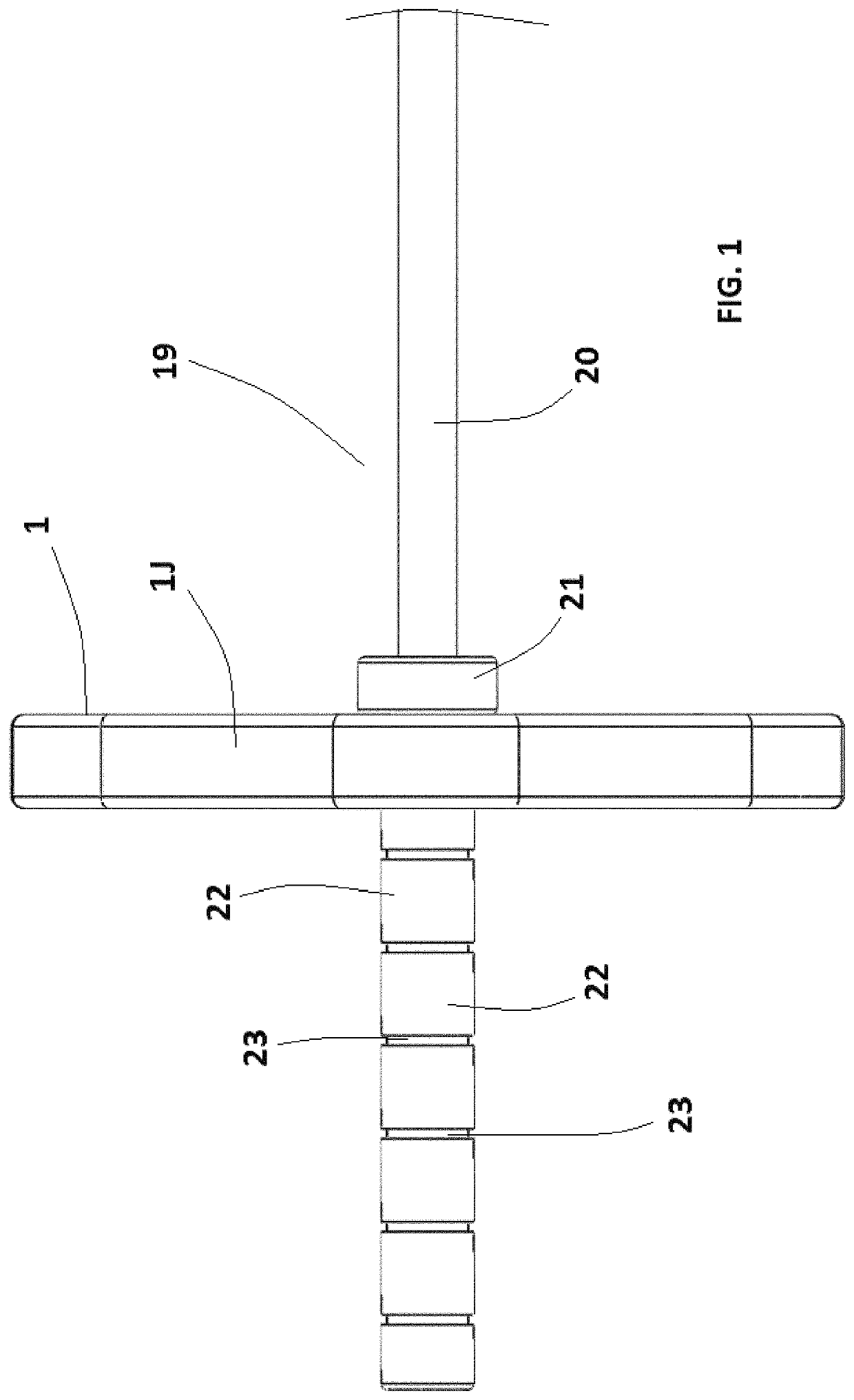
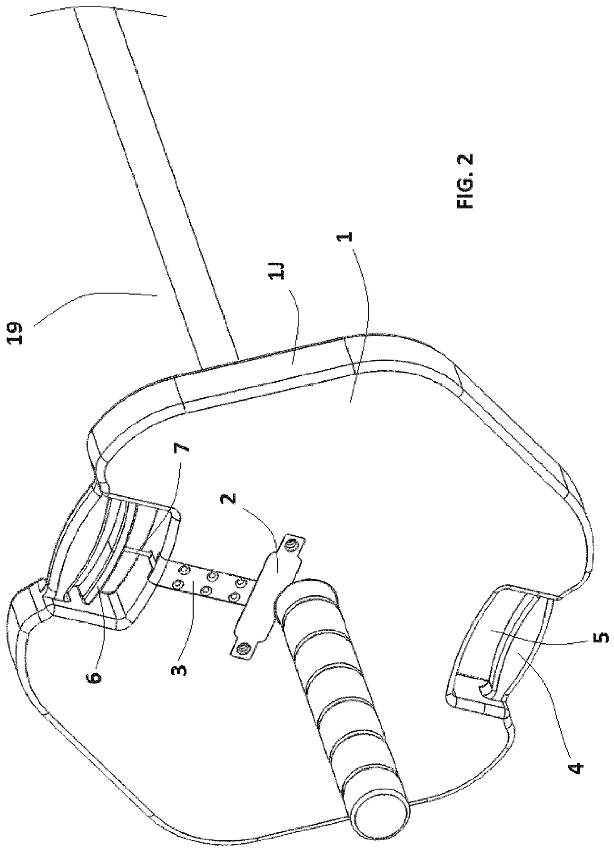
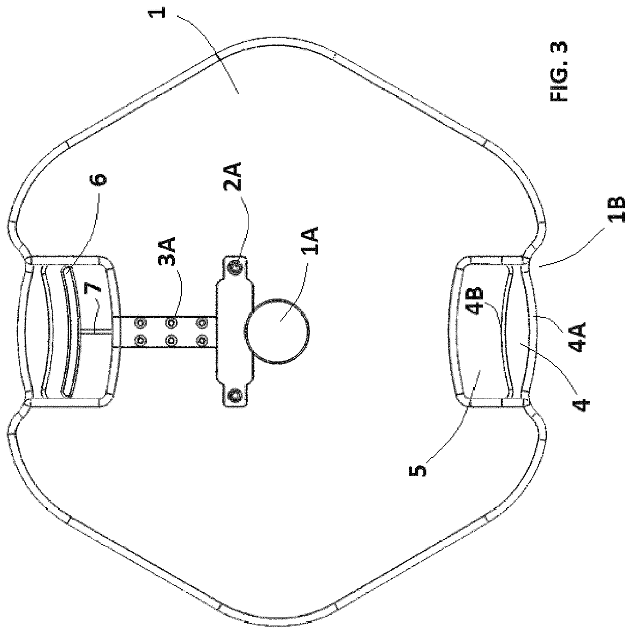
[0039]The figures illustrate a weight plate 1 having weight plate outer edge 1J, which may be releasably fastened and removed from a barbell 19. The weight plate 1 comprises a lock assembly case 2, and a pull rod casing 3. Further, the weight plate 1 comprises a pair of handles 4, which are preferably, but not necessarily, on opposing sides of the weight plate 1, the handles 4 typically being located within or defining a hand space 5. A release and lock pull lever 6 is located within a hand space 5. A pull rod 7 is fastened to the release and lock pull lever 6, and is accommodated over substantial part of the length within a pull rod tube 8.

[0040]The weight plate 1 further comprises a lock plate plug 9 (clearly seen in FIG. 5 of the drawings), and a lock plate 13 which engages with the barbell...


PUM


Abstract

A barbell comprises a substantially cylindrical elongated bar having a plurality of connectors located along the length thereof. A generally disk shaped weight plate having a central aperture and a peripheral handle is provided, and the barbell is received within the central aperture. A fastening assembly is formed on the weight plate and extends between the central aperture and the peripheral handle. The fastening assembly is selectively movable between a first position in which it engages with one of the connectors on the barbell, and a second position in which it is disengaged from the connector on the barbell.

Description

CROSS-REFERENCE TO RELATED APPLICATIONS[0001]This application is a continuation in part application of U.S. patent application Ser. No. 15 / 964,539 filed Apr. 27, 2018, which claims the benefit of U.S. Provisional Patent Application No. 62 / 491,247 filed Apr. 27, 2017, the contents of which are incorporated herein by reference in their entirety.FIELD AND BACKGROUND OF THE INVENTION[0002]Exercise has been strongly in the public arena for the better part of the last 70 years, from Jack LaLanne to Arnold Schwarzenegger and beyond. The fitness industry has boomed and grown substantially over the years, and there are gyms which come in every size and shape, from single location gyms to chains that have over a thousand locations. While the items available for “working out” have changed many times over, there are still a few pieces of exercise equipment that are constant and that endure.[0003]One of the best examples of an enduring workout item would be in the area of free weights, those bei...

Claims


Application Information

Patent Timeline
IPC IPC(8): A63B21/072A63B21/06A63B71/00
CPCA63B21/0728A63B21/0604A63B21/0724A63B71/0036
Inventor BAKER, SCOTT BRADLEY
Owner BAKER SCOTT BRADLEY
Learn More